BrailleRAP building manual
Necessary tools
Small pliers.
Small cutting pliers.
M3 tap.
8mm drill.
3mm drill.
Hex keys 1.5, 2, 2.5 and 4.
Tube wrenches 5.5 and 8.
Wood glue.
Blue painter’s tape.
Notes on screws
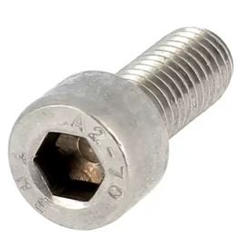
M3 and M5 refer to the diameter in mm of the threaded part of the screws. The second number corresponds to the length of the screw. For example M3-12 means a screw 3mm in diameter and 12mm in length
M5-18 refers to a hex head screw (5mm in diameter 18mm in length)
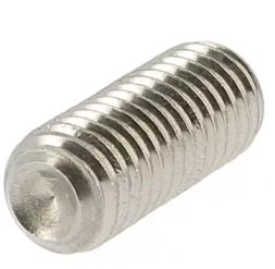
M3-12 grub refers to a grub screw (3mm diameter - 12 mm length)
Notes on nuts
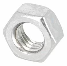
M3 nut or M5 nut refers to standard nuts with a diameter of 3mm or 5mm
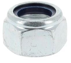
M3 nyloc nut or M5 nyloc nut refer to locking nuts of diameter 3mm or 5mm
Notes about BrailleRAP/BrailleRAP XL
BrailleRAP now exist in 2 differents models : BrailleRAP and BrailleRAP XL.
BrailleRAP is the original version and can use paper sheet in A4 or smaller.
Braillerap_v6-5-1_600x400-planche1.svg
Braillerap_v6-5-1_600x400-planche2.svg
BrailleRAP XL is a larger version, and can use paper sheets A3 or smaller.
brapxl-v6-6-planche1_900x400.svg
brapxl-v6-6-planche2_900x400.svg
Assembly of the 2 versions is mostly similar. The main differences are:
Bonding of the paper tray.
The number of paper rollers.
the length of the linear rods and belts.
BrailleRAP XL requires more precise mechanical assembly.
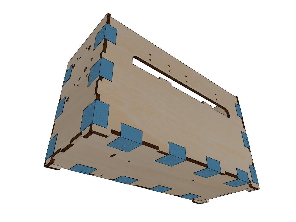
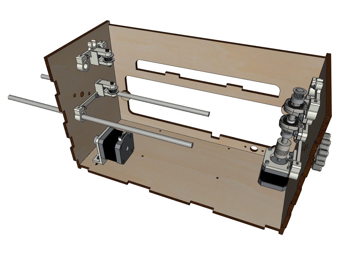
Wooden enclosure assembly
Material:
FACE (5mm laser cut plywood).
BACK (5mm laser cut plywood).
BOTTOM (5mm laser cut plywood).
LEFT_SIDE (5mm laser cut plywood).
RIGHT_SIDE (5mm laser cut plywood).
Wood glue.
Blue painter’s tape.
Prepare the 5 parts: FACE, BACK, LEFT_SIDE, RIGHT_SIDE and BOTTOM.
Attention
Carefully identify the orientation of the sides (right and left) and the bottom. Use the holes to orient the parts as shown in the figure

Glue the notches and assemble the 5 parts, then secure with painter’s tape until the glue is fully dry, according to manufacturer’s instructions.
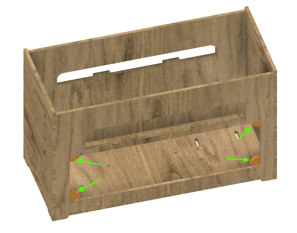
Gluing the door stops
Material:
Assembled wooden enclosure.
4 wooden discs saved from laser cutting the lid.
Wood glue.
Glue the 4 wooden discs to the interior of the back side of the enclosure. These discs will hold the access hatch inside the machine.
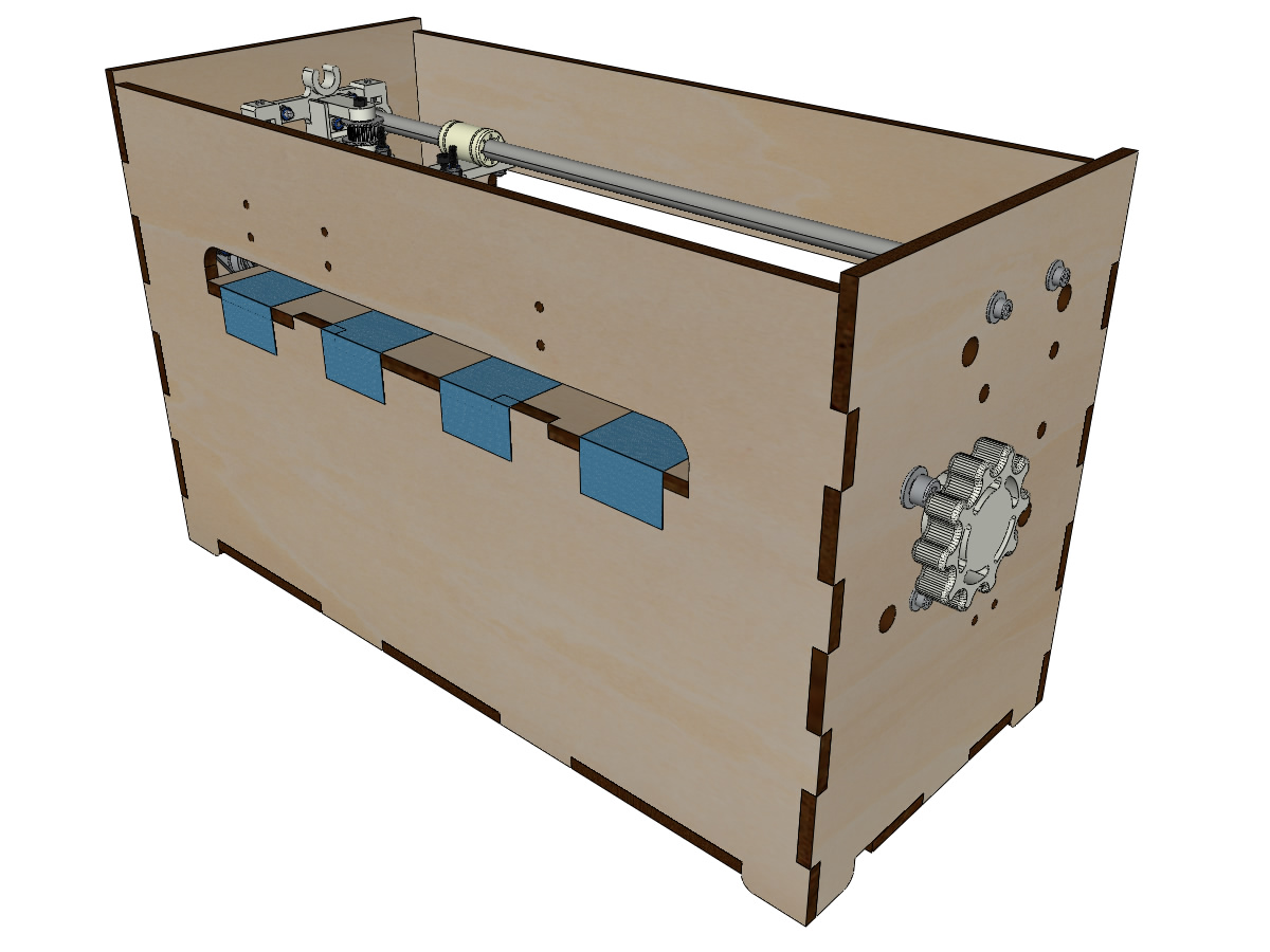
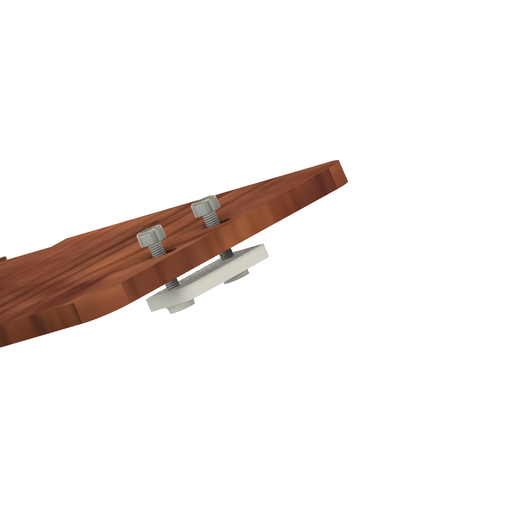
Bonding the paper tray
- Material:
Upper paper support.
Lower paper support.
Wood glue.
Clamping Pliers.
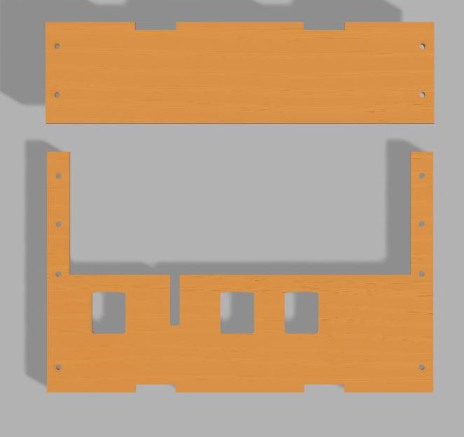
Glue the lower support to the underside of the upper support.
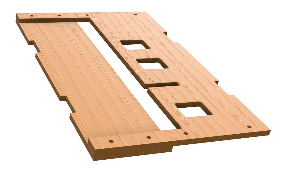
Attention
The 2 parts must be perfectly aligned. Place screws in the holes to properly align the parts. There must not be any space between the two pieces (or the paper could catch and jam there). Clamp the parts together tightly
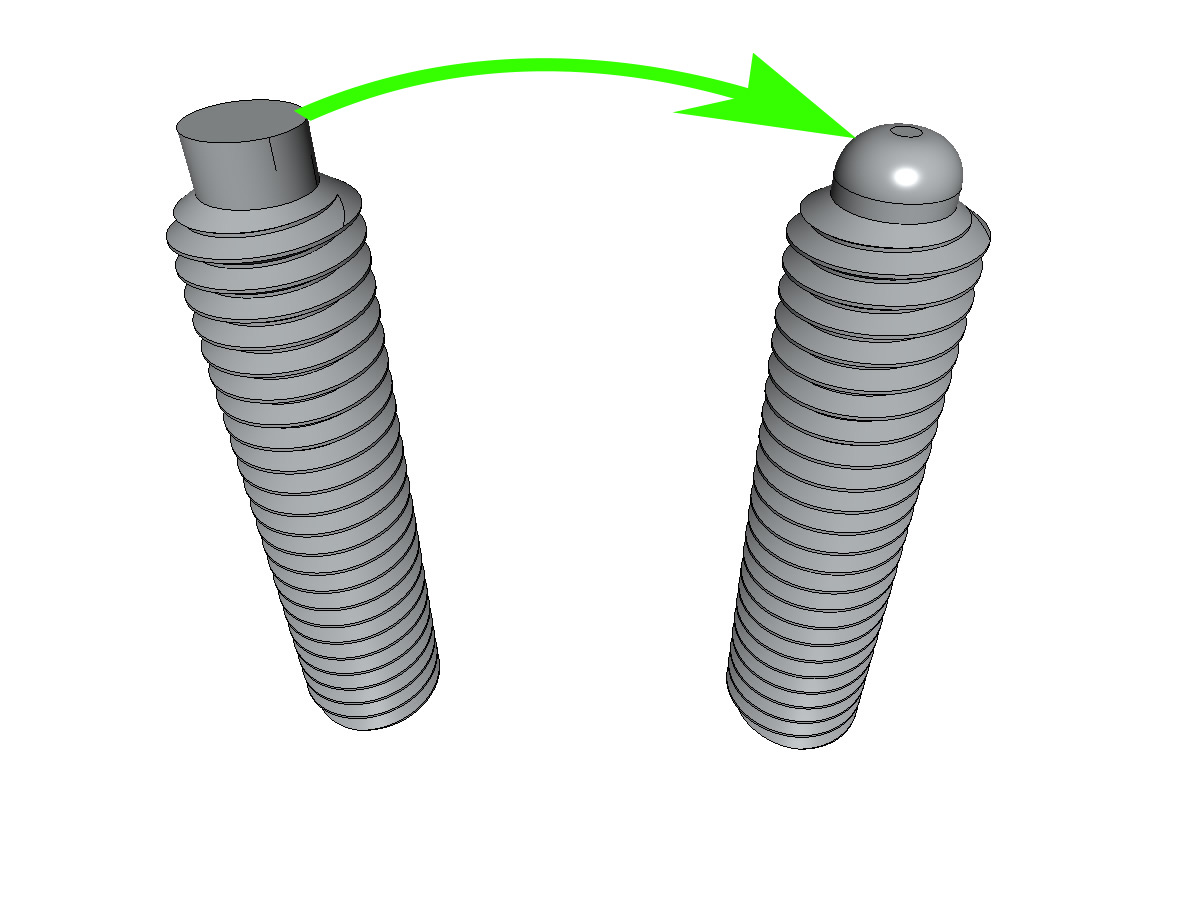
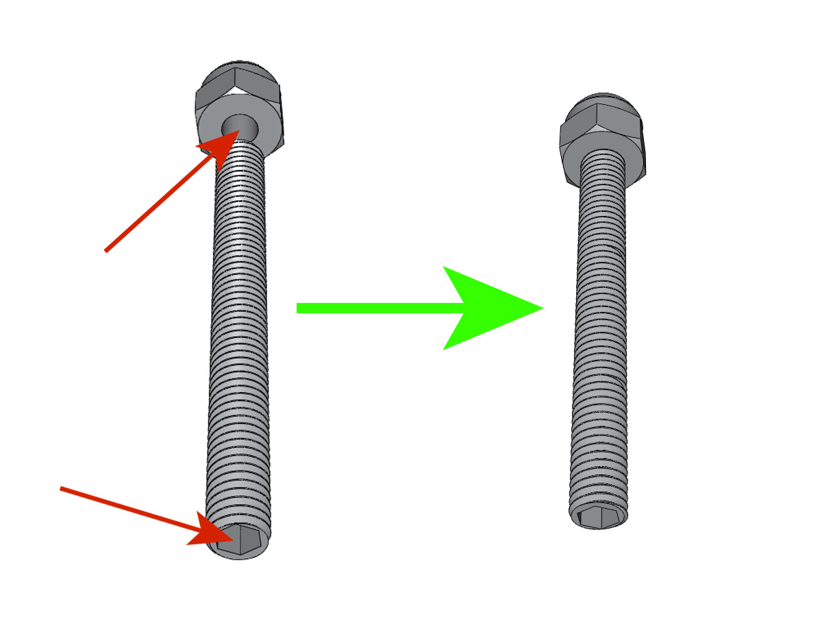
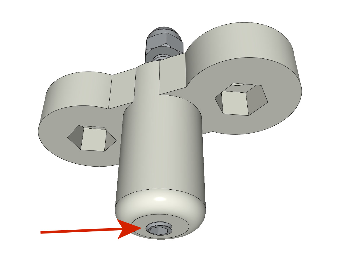
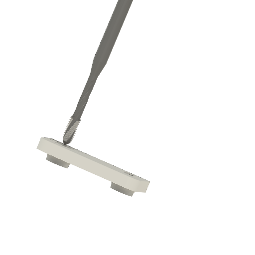
Preparation of the Braille stylus
Equipment:
1 Whetstone
1 dog point grub screw M3-16
File down the edge of the tip to match the illustrated shape.
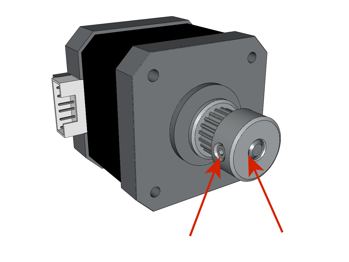
X Motor preparation
Equipment:
3D printed parts : XMOTOR_support3 or XMOTOR_support3_1
1 Nema 17 motor
4 M3-8 screws
2 M3 nyloc nuts
2 M3-14 screws
Insert the 2 M3 nyloc nuts into the printed part XMOTOR_support3_1.
Join the two printed parts XMOTOR_support3_1 and XMOTOR_support3 with two M3-14 screws.
Mount the motor into its support with 4 M3-8 screws. Don’t tighten the screws, as the motor needs some play for adjustment and will be secured later.
Note
Carefully note the position of the motor connector!
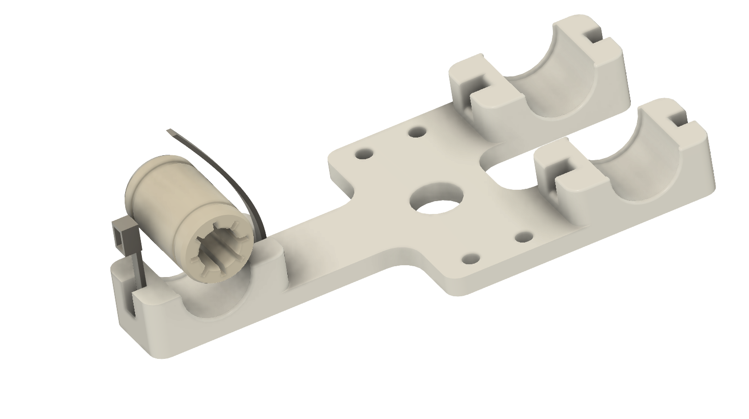
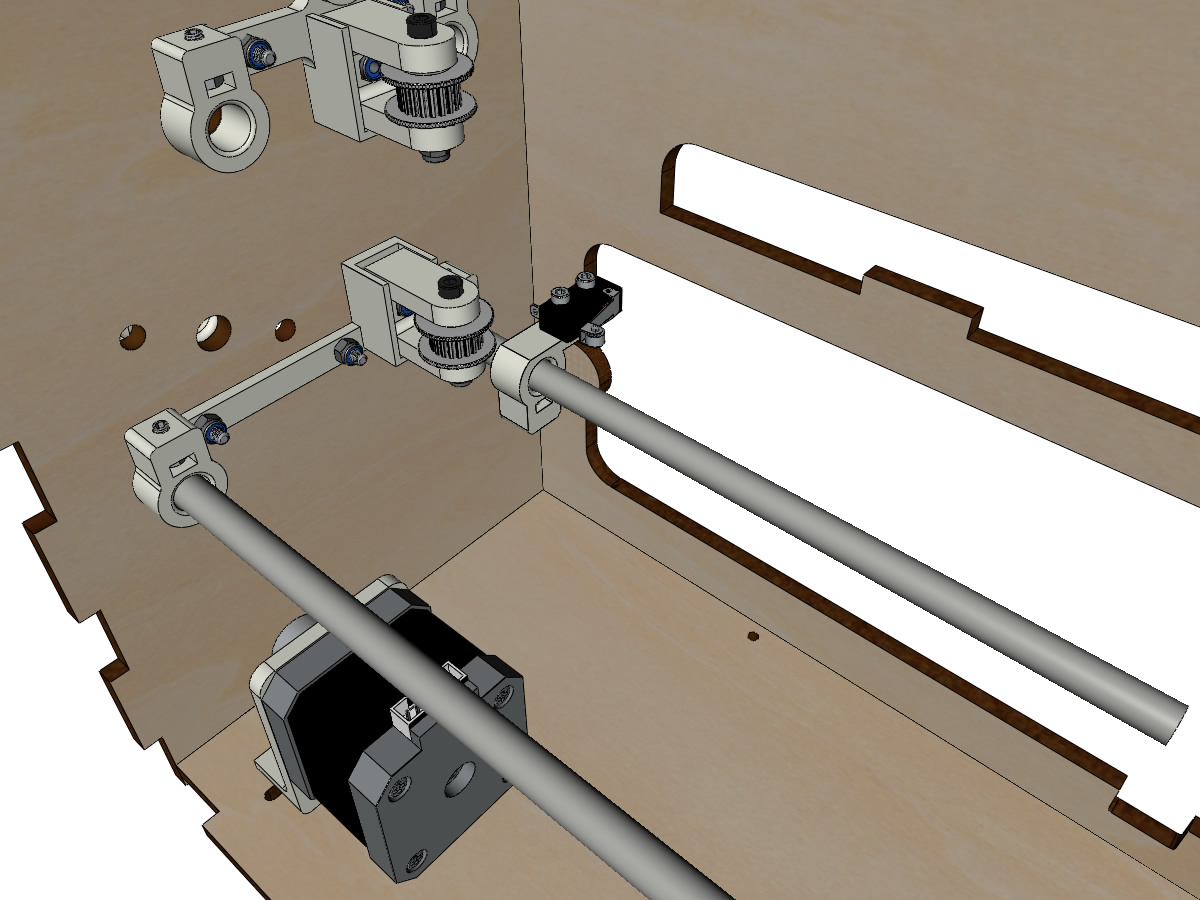
Y Motor preparation
Equipment:
3D Printed parts: YMOTOR_support2_200_1, YMOTOR_support2_200_2, YMOTOR_support2_200
1 Nema 17 motor
1 GT2 pulley, 20 teeth, 5mm bore
4 M3-8 screws
2 M3-12 screws
Screw the pulley onto the motor shaft, making sure that at least one of the two screws is in front of the flat part of the motor shaft and that the teeth of the pulley are facing towards the motor.
Tap both sides of the middle part of the support (YMOTOR_support2_200_2)
Attach the two printed parts YMOTOR_support2_200_2 and YMOTOR_support2_200_1 with M3-12 screws.
Attach the part YMOTOR_support2_200 to the previous two with an M3-12 screw.
Mount the motor into its support with the 4 M3-8 screws, making sure that the connector is in the position shown in the illustration.
Insert the 4 M3 nyloc nuts into the motor mount. Hold them in place with a small piece of painter’s tape.
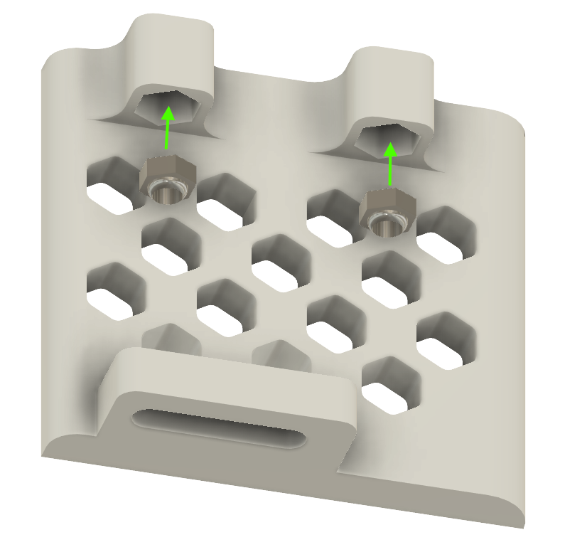
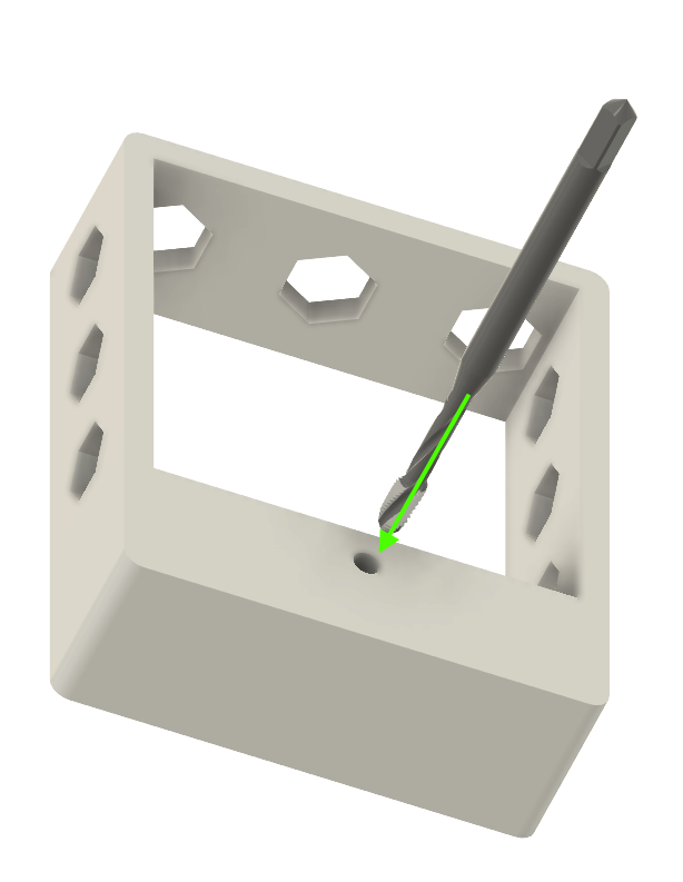
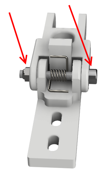
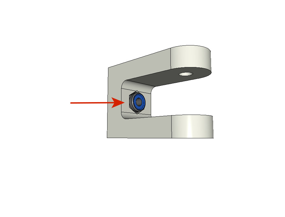
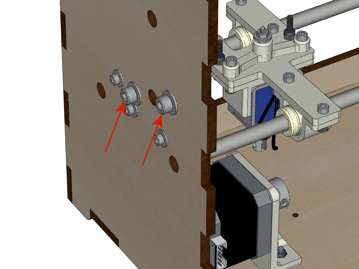
Axis supports preparation
3D printed parts : BOTTOM_AXIS_left2
3D printed parts : TOP_AXIS_left2
3D printed parts : TOP_AXIS_right2
1 8mm drill
6 M3 nuts
6 M3-12 grub screws
Attention
Check that the 8mm rods slide easily into their holes, as their size may vary depending on the print quality of the plastic parts. If necessary, drill out the holes with an 8mm bit.
The 3 parts to be assembled are as follows
Insert an M3 nut into each of the rectangular holes in all 3 parts. Thread in the M3-12 grub screws.
The end of the screw must not extend into the hole for the Ø 8mm bars.
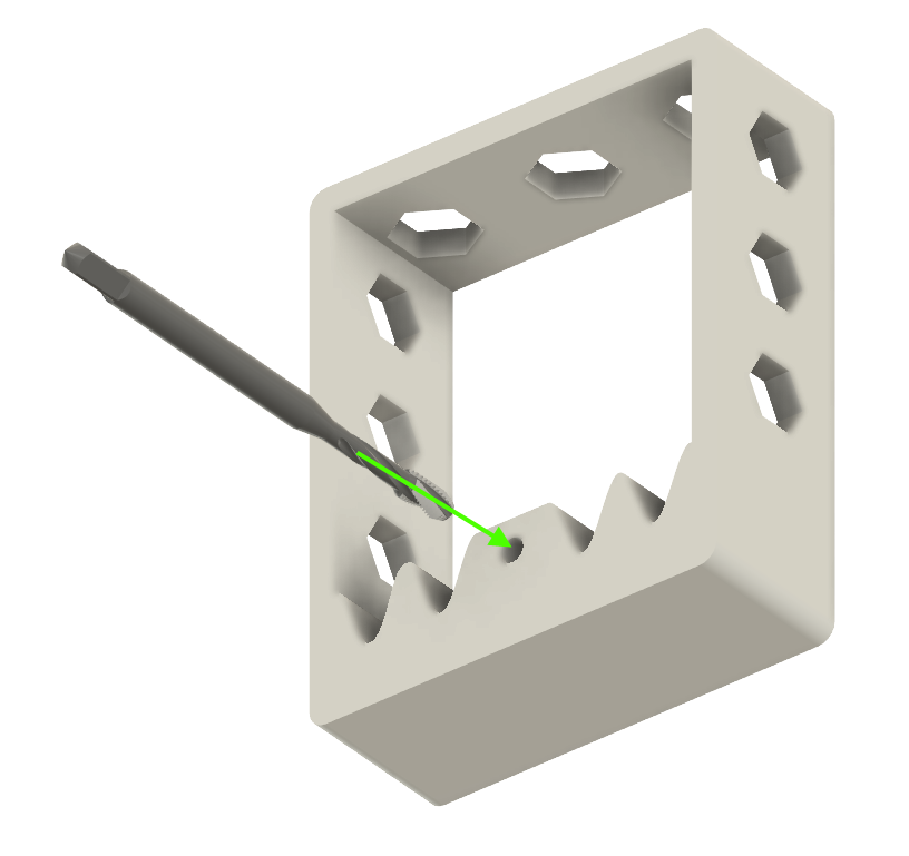
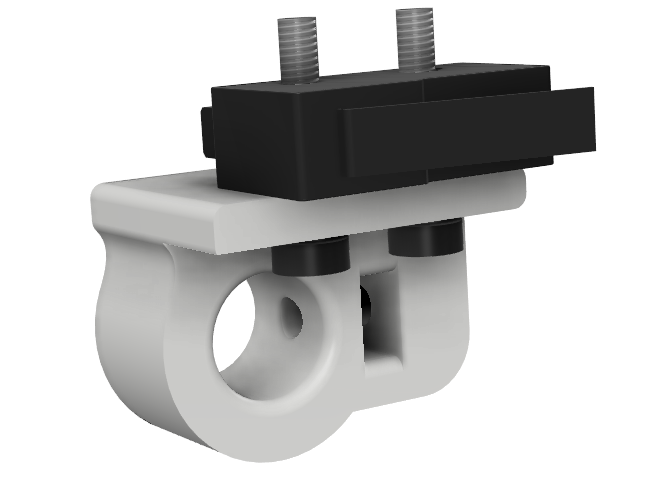
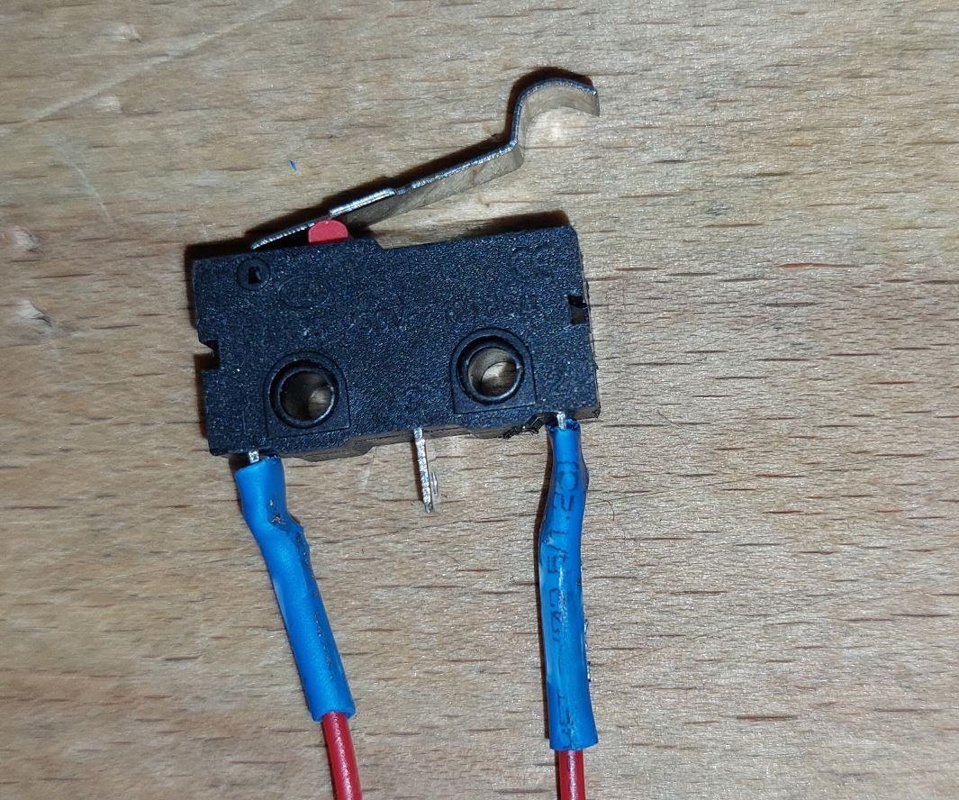
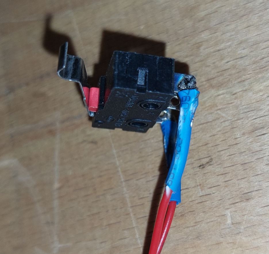
Limit switch X preparation
Equipment:
3D printed parts : SWITCH_X_support
1 wired limit switch (see wiring of the limit switches)
1 M3-12 grub screw
1 M3 nut
2 M2.5-14 screws
2 M2.5 nyloc nuts
Insert an M3 nut, and thread in an M3-12 grub screw.
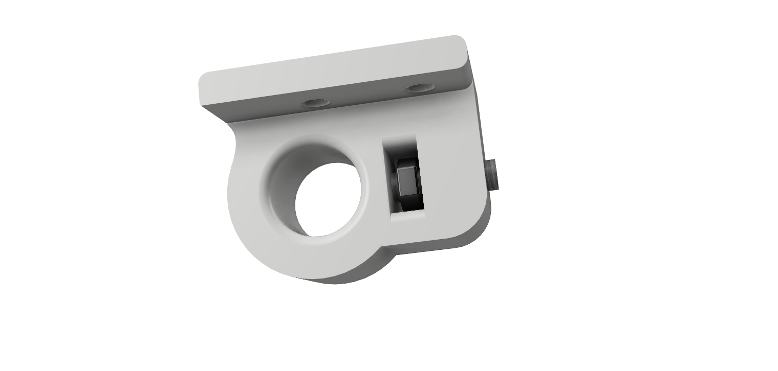
Attach the limit switch to its support (SWITCH_X_support) using M2.5-14 screws and M2.5 nuts.
Note
The limit switch is pictured without wires, but must be wired before assembly.
Note
Note the position of the M2.5 screws. The head of the screw must be under the limit switch to give clearance for the linear rod.
Note
It’s better to use a straight aligned wired endswitch.
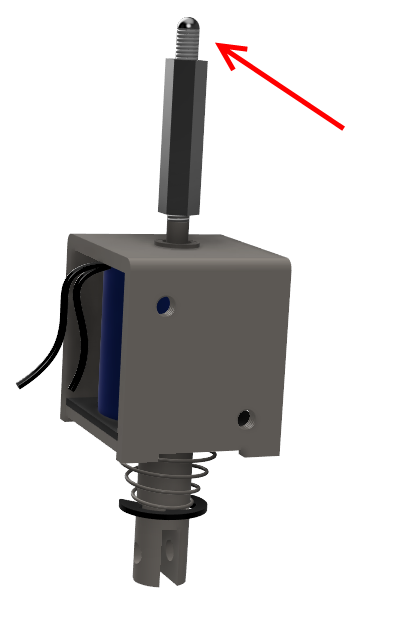
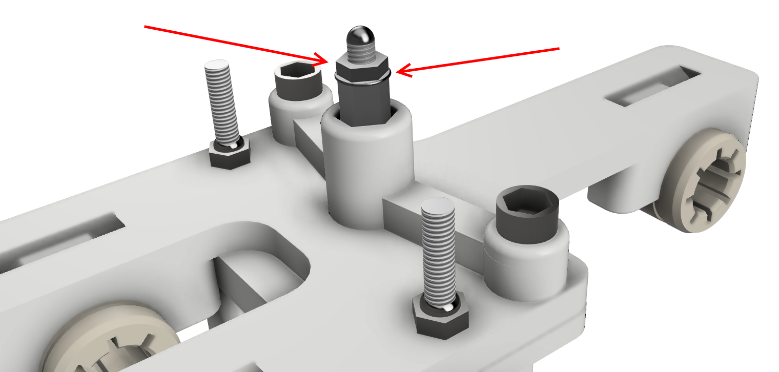
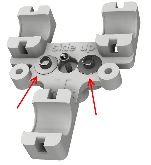
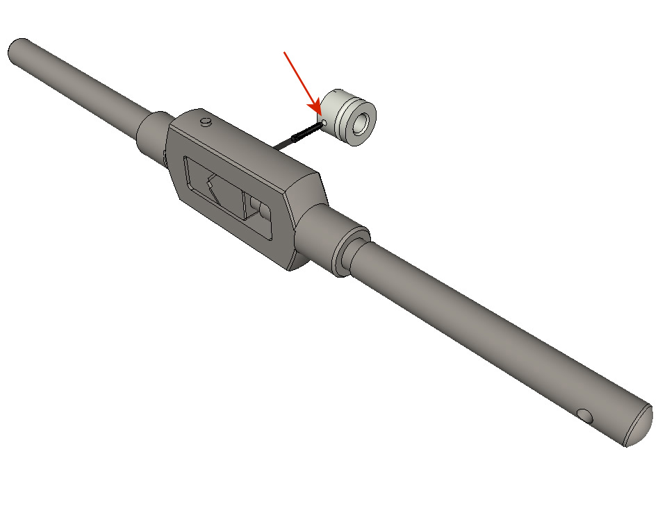
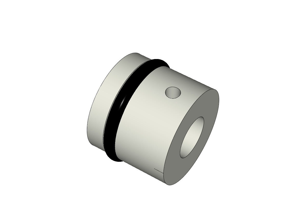
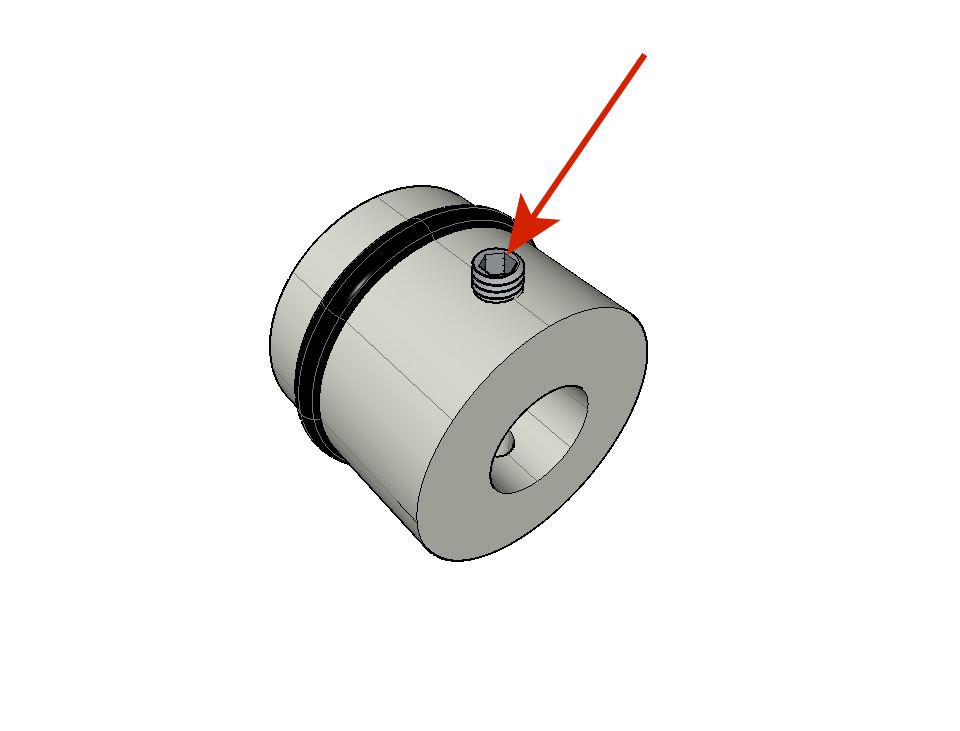
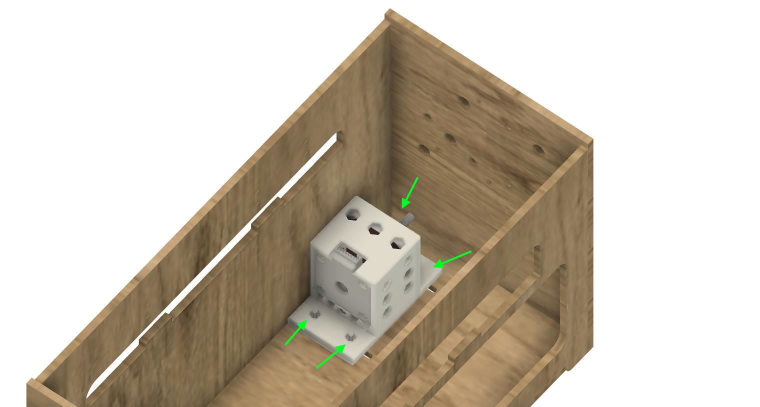
Solenoid preparation
Equipment:
1 solenoid
1 18mm spacer
1 M3-16 grub screw with shaped tip (see Preparation of the Braille stylus)
1 M3 nut
1 M3 washer
Screw the spacer all the way onto the electromagnet.
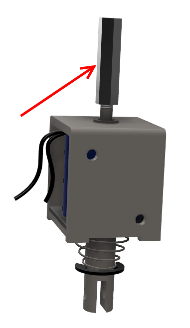
Tighten the M3-16 screw with the Braille stylus punched out, allowing it to extend ± 6mm beyond the spacer.
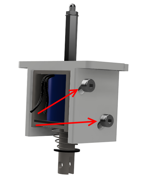
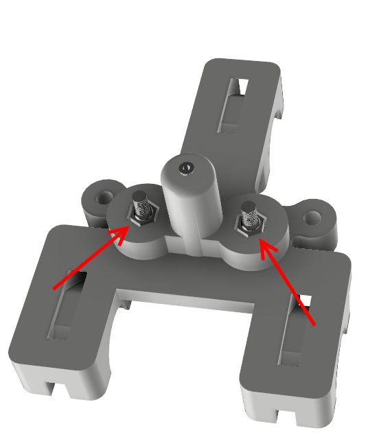
Solenoid assembly
- Equipment:
Pre-assembled solenoid assembly (see Preparing the electromagnet)
3D printed parts : ELECTRO_MAGNET_housing2 or ELECTRO_MAGNET_Housing2_fit
2 screw M3-8
2 M3 washers
Select either ELECTRO_MAGNET_housing2 or ELECTRO_MAGNET_Housing2_fit. On an older generation 3D printer, ELECTRO_MAGNET_housing2 is preferred. On a modern, ultra-precise printer, ELECTRO_MAGNET_Housing2_fit is preferred. These are the same parts, but the mechanical tolerances are tighter on the fit version, allowing for better centering of the solenoid.
Fix the solenoid on its support with the 2 screws M3-8 and 2 M3 washers.
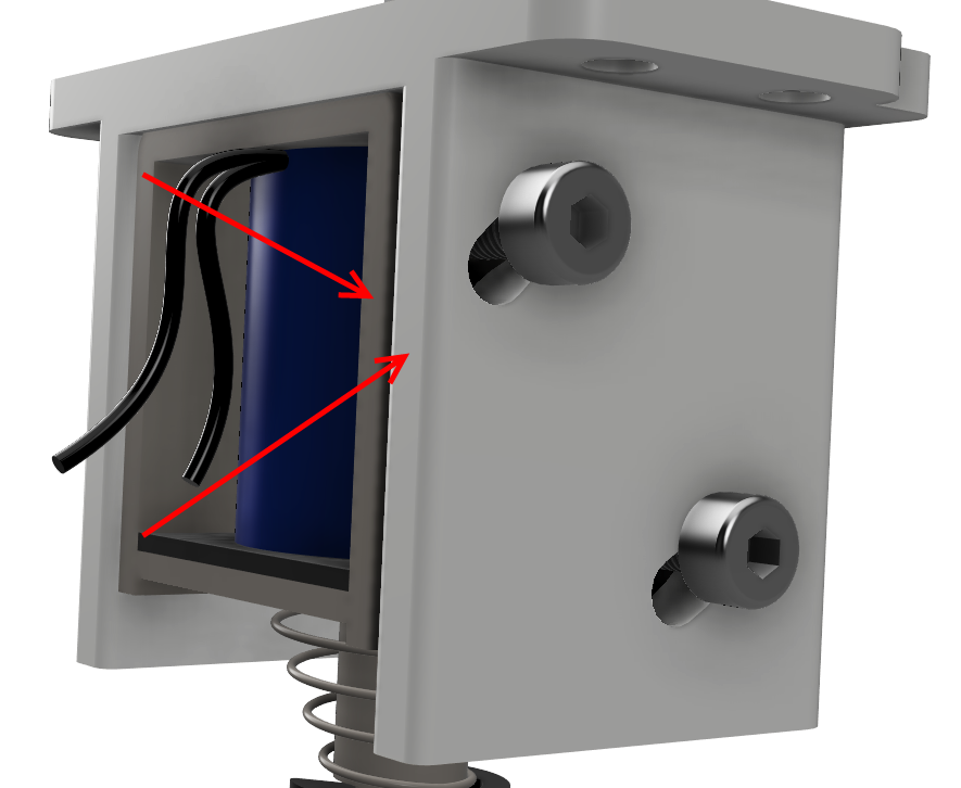
Attention
Observe the exit side of the wires.
Note
Be sure to carefully align the edge of the plastic part and the edge of the electro magnet
Bottom truck prepare (step 1)
Equipment:
Solenoid assembled in its support
3D printed part : BOTTOM_trolley
3D printed parts: ELECTRO_MAGNET_guide_fitxxx
3 IGUS linear bearings
3 clamps 2.5 x 160
4 M3 nyloc nuts
2 M3-16 screw
2 M3-20 screw
Note
Select the best part between ELECTRO_MAGNET_guide_fit_5.8 / ELECTRO_MAGNET_guide_fit_5.9 / ELECTRO_MAGNET_guide_fit_6.0. the spacer must move freely with the less tolerance.
Introduce the 3 IGUS on the BOTTOM_trolley support. Fix them with clamps
Attention
Lock the IGUS in the groove. Do not overtighten the clamps,they will be adjusted when the carriage is in place on the linear rails
Attention
Respect the position of the clamps. The locking of the clamps must be on the IGUS side and towards the front of the machine.
Assemble the electromagnet (previously mounted in its housing) under the BOTTOM_trolley and the ELECTRO_MAGNET_guide with two M3-16 screws and two M3 nyloc nuts.
Attention
Depending on the quality of the print, it may be necessary to file the spacer housing. Also note that the body of the electro-magnet must be as perpendicular as possible to the support plate(the axis must be in the middle of the drilling which allows its passage).
Attention
Note that the wires of the electromagnet must come out of the side where there is a single IGUS bearing.
Screw the two M3-20 screws (which will hold the strap) and 2 M3 nyloc nuts with the screw head underneath.
Fit a washer and tighten the M3 lock nut, ensuring that the stylus screw does not move into the spacer at the same time. The washer prevents the jam nut from getting caught in the spacer guide.
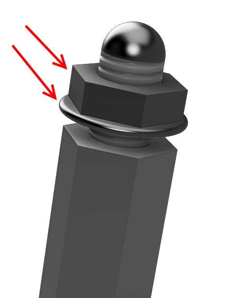
Note
The axis of the electromagnet must be able to move up and down freely without resistance.
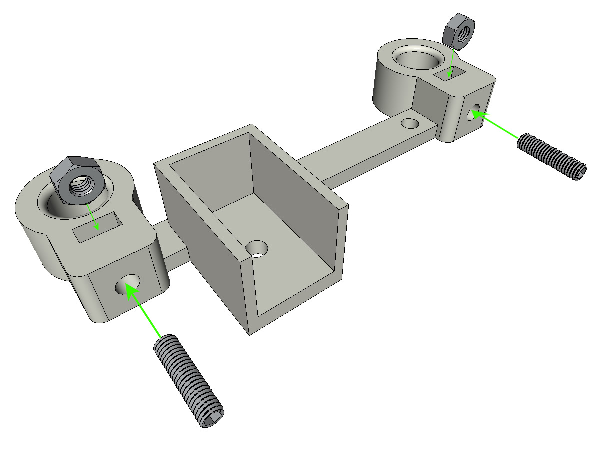
Mounting the top cart (step 1)
Equipment:
3D printed parts: TOP_trolley
3D printed parts: FEMALE_shape
M3 tap
1 M3-30 grub screw
1 M3 blind nut
1 M3 nut
2 M3-12 screws
2 M3 washers
2 M3-20 screw
4 M3 nyloc nuts
3 IGUS linear bearings
3 clamps 2.5 x 160
Glue the thread of the cap nut and screw the M3-30 screw without head on the side WITHOUT hex hole.
Put a lock nut on the blind nut
Tape the FEMALE_shape 2/3 from the top.
Tighten the M3-30 screw / blind nut assembly to allow it to exceed ± 0.5mm.
Assemble the FEMALE_shape on the TOP_trolley with the M3-12 screws, the M3 washers and the M3 nyloc nuts.
Position the IGUS bearings on the TOP_trolley part.
attach the IGUS bearings with fixing collars
Note
Pay attention to the direction of the clamps. The clamp fixing must be towards thewalls of the machine.
Note
Lock the IGUS in the groove. Do not overtighten the clamps,they will be adjusted when the carriage is in place on the linear rails
Fit the M3-20 screws and the M3 nuts.
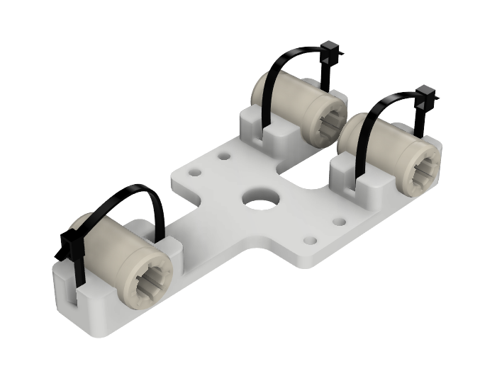
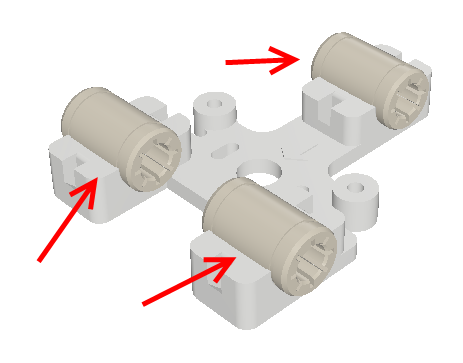
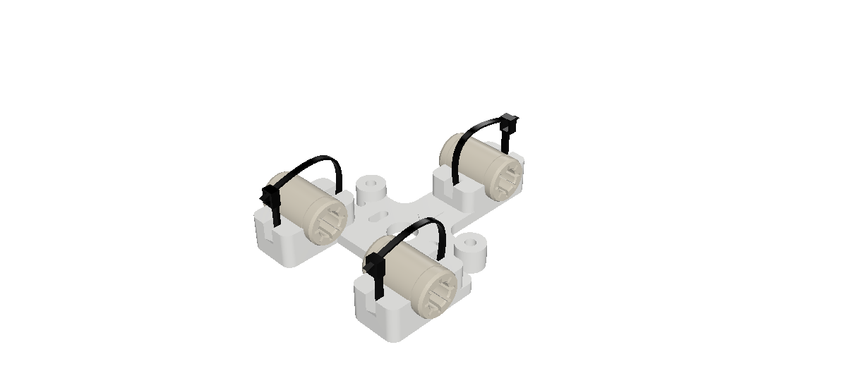
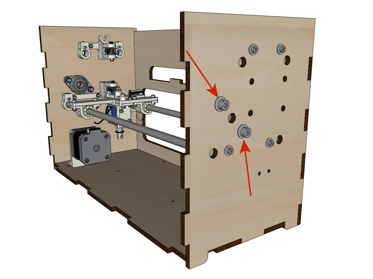
Paper roll prepare
Equipment BrailleRAP:
3D printed parts: 3 x ROLL_joint3
1 tap M3
3 O-rings
5 M3-6 grub screw
Equipment BrailleRAP XL:
3D printed parts: 4 x ROLL_joint3
1 tap M3
4 O-rings
8 M3-6 grub screw
Tap the 3 or 4 ROLL_joint3.
Put the O-rings in the groove of the 3 or 4 ROLL_joint3.
Screw in the M3-6 grub screws making sure they do not protrude at inside the hole. You need to be able to slide the roll over a 8mm axle.
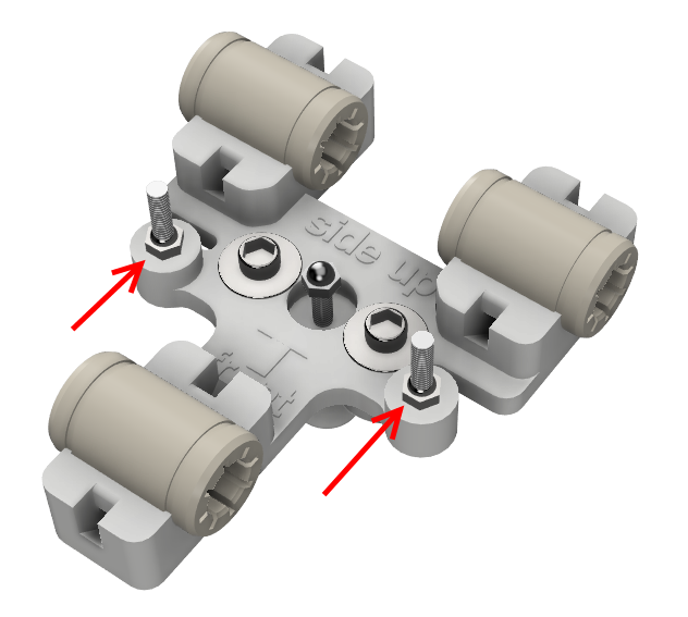
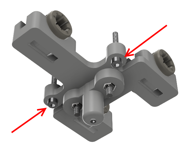
Assembly of the paperweights (step 1):
Equipment BrailleRAP:
3D printed part(s): 3 x clipboard2_support 3 x clipboard2 3 x CLIPBOARD2_WHEEL
3 M3-25 screw
3 M3-20 screw
3 GT2 belt tensioner springs
6 M3 nyloc nuts
Equipment BrailleRAP XL:
3D printed part(s): 4 x clipboard2_support 4 x clipboard2 4 x CLIPBOARD2_WHEEL
4 M3-25 screw
4 M3-20 screw
4 GT2 belt tensionner springs
8 M3 nyloc nuts
Position the clipboard clipboard2 in relation to the support clipboard2_support.
Position the spring between clipboard2 and clipboard2_support.
Assemble the spring with clipboard2 and clipboard2_support with an M3-25 screw and an M3 nyloc nut.
Note
Do not tighten the M3 nyloc nut clipboard2 and clipboard2_support must be able to move freely.
Assemble roller with CLIPBOARD2_WHEEL with clipboard2 using an M3-20 screw and an M3 nyloc nut.
Note
Do not tighten the M3 nyloc nut CLIPBOARD2_WHEEL must be able to turnfreely.
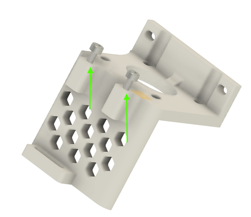
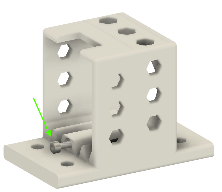
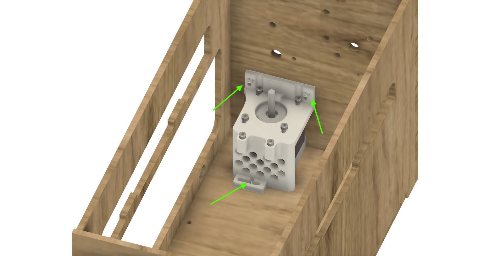
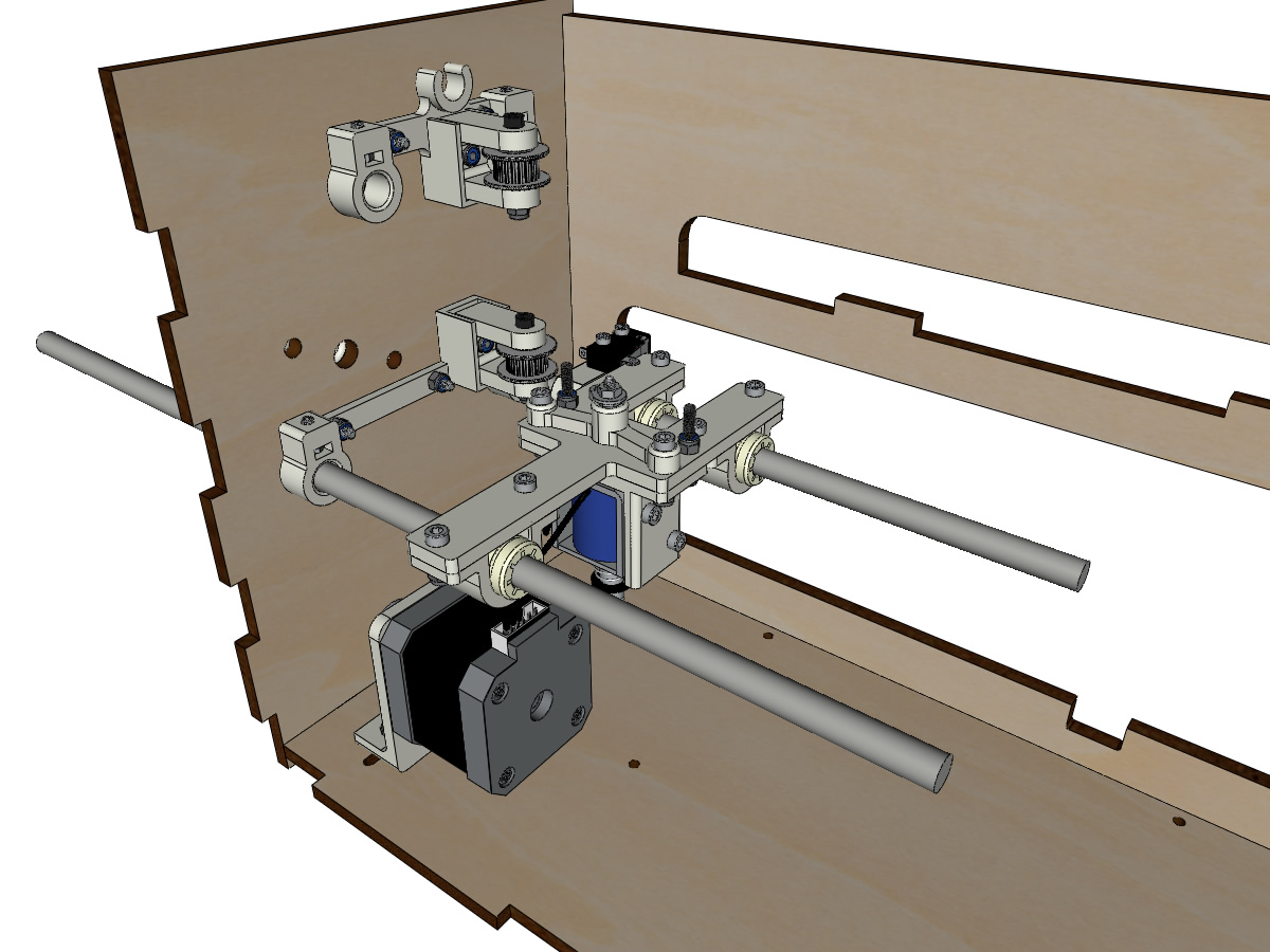
Vertical axis setup (step 1)
Equipment:
parts: assembled XMOTOR_support2, XMOTOR_support2_1 and stepper motor
2 M3-20 screw
2 M3 nyloc nuts
2 wide M3 washers
Insert the 2 screws and the 2 washers from the outside. And attach the bracket with 2 NYL nuts without tightening.
Note
The gap will then allow to align the motor shaft with the vertical axis.
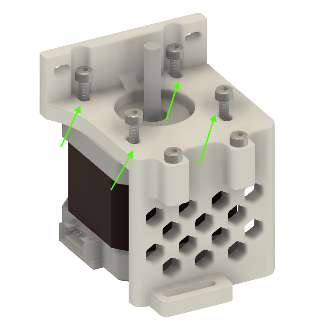
Y Motor Mount:
Equipment:
the Nema17 stepper motor mounted on YMOTOR_support2_200 + YMOTOR_support2_200_1 + YMOTOR_support2_200_2
4 M3-14 screws
4 wide M3 washers
Insert the screws and washers from the outside and screw the support onto the crate so that it can still slide in the oblong holes.
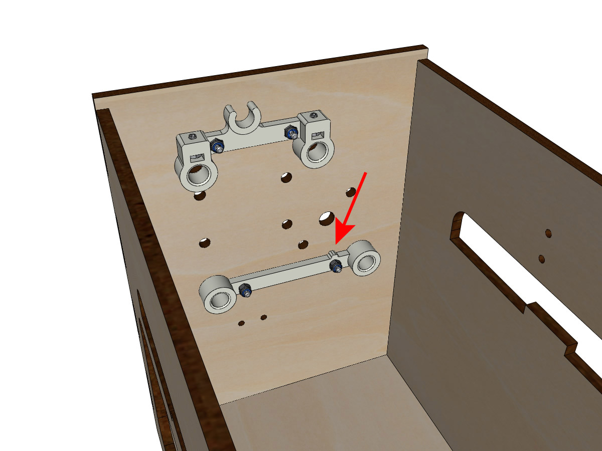
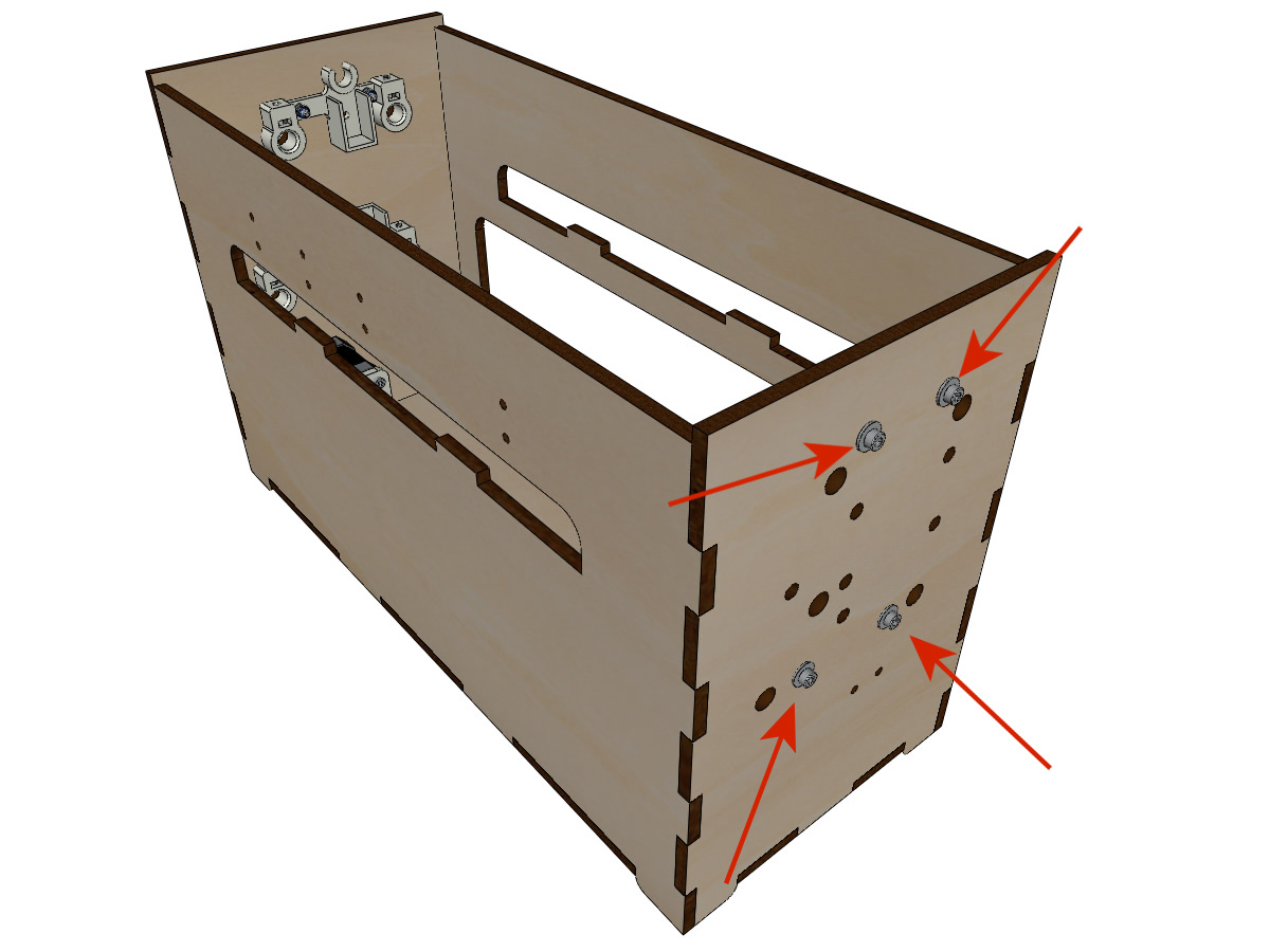
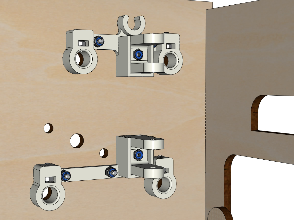
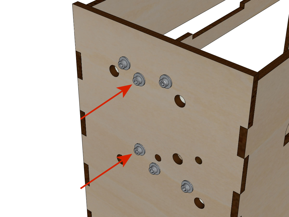
Assembling LEFT shafts supports
Equipment:
3D printed parts: BOTTOM_AXIS_left2 prepared with nut and grub screw (see Preparation of axle supports)
3D printed parts: TOP_AXIS_left2 prepared with nut and grub screw (see Preparation of axle supports)
4 M3-14 screws
4 wide M3 washers
4 M3 nyloc nuts
Fix the supports of axis on the box the BOTTOM_AXIS_left2 and TOP_AXIS_left2 on the left leaving a little game (screw + washer outside and nut inside). The screws will be tight when the assembly is in place.
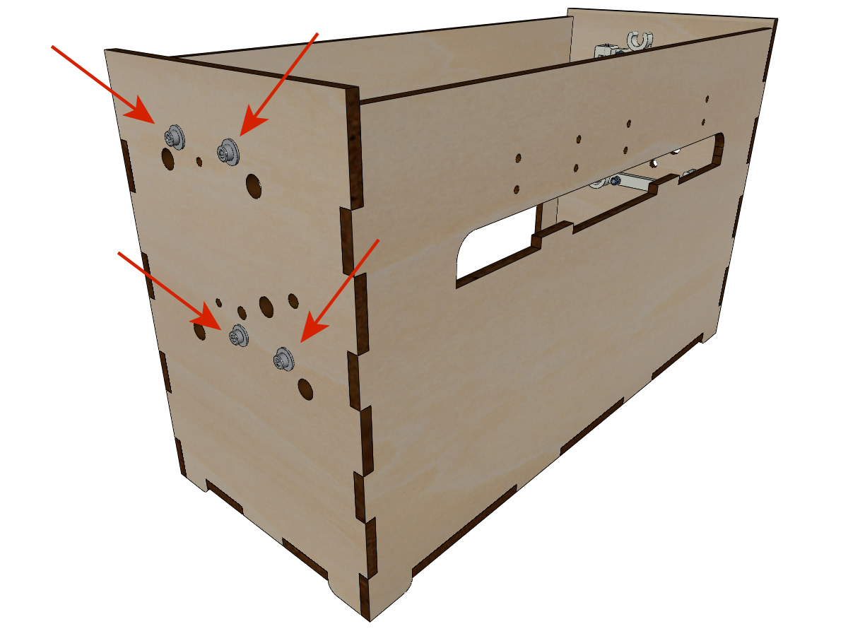
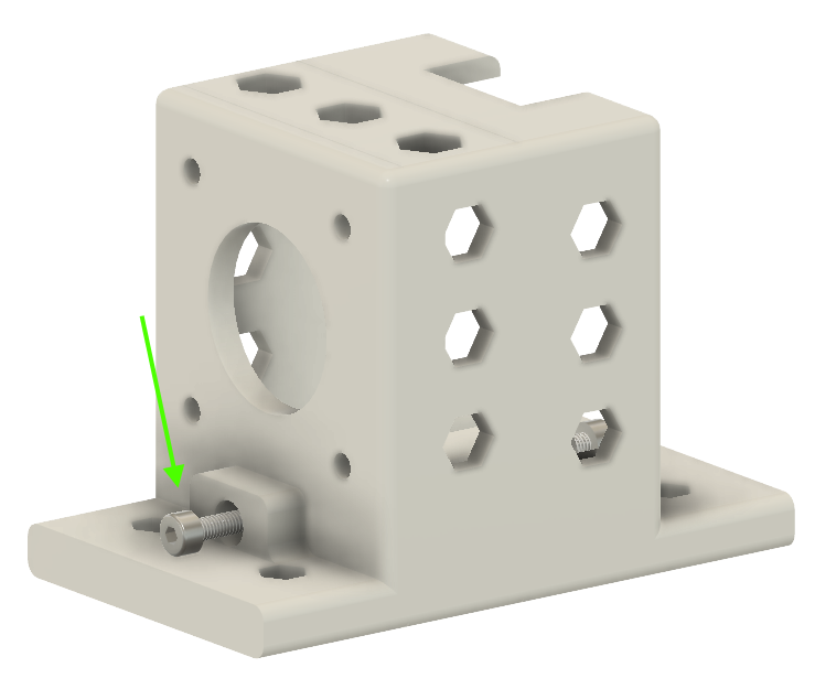
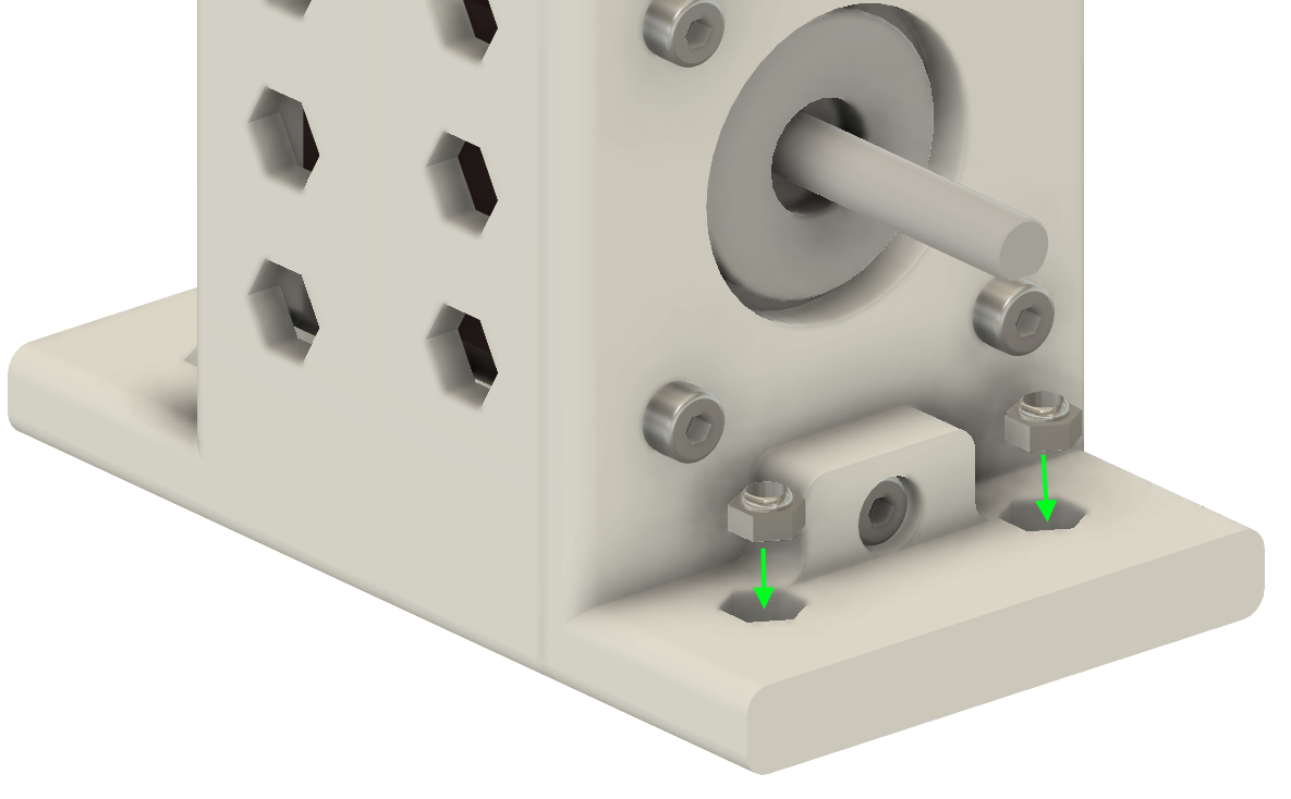
Assembling RIGHT rod supports
Equipment:
3D printed parts : BOTTOM_AXIS_right2
3D printed parts: TOP_AXIS_right2 prepared with nut and grub screws (see Preparation of axis supports)
4 M3-14 screws
4 wide M3 washers
4 M3 nyloc nuts
Fix rod supports on the box with BOTTOM_AXIS_right2 and TOP_AXIS_right2 on the right with leaving some mechanical clearance (screw + washer outside and nut inside). The screws will be tight when all parts will be in place.
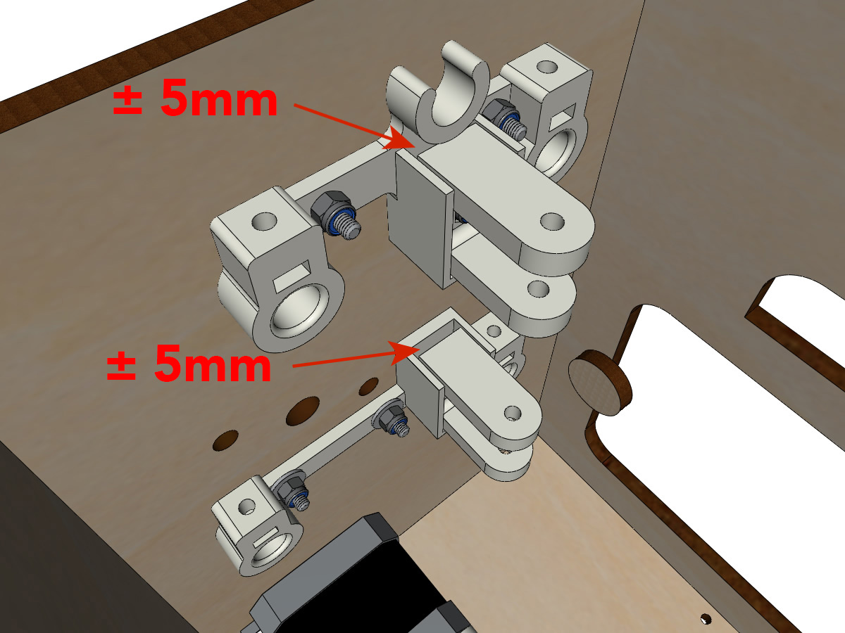
Fastening the belt tensioners
Equipment:
3D printed parts : 2 x DRIVEN_PULLEY_housing
2 M3-20 screw
2 wide M3 washers
2 M3 nyloc nuts
Insert a NYL M3 nut into its housing and secure the DRIVEN_PULLEY_housing with a M3-20 screw and washer.
Leave a gap of ± 5mm.
Free pulleys assembly
Equipment:
2 free pulleys 20 teeth 3mm bore
2 M3-25 screw
2 M3 nyloc nuts
Start by inserting the pulley then the M3-25 screw. Screw with a NYL M3 nut without tightening too much.
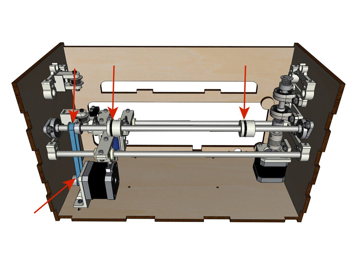
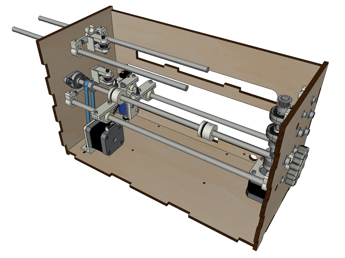
Bottom carriage assembly (step 2)
Equipment BrailleRAP:
2 linear shaft Ø8mm, length: 330mm
Equipment BrailleRAP XL:
2 linear shaft Ø8mm, length: 470mm
Note
We did not represent the facade for readability reasons.
Push the bars halfway through the outside of the frame.
Push the endstop and its support on the Ø8mm bar on the back side.
Note
The screw on the switch bracket will be tightened later during adjustment.
Push the bottom carriage over the smooth bars.
Finish putting on the bars (the bars must not protrude into the wood of the box).
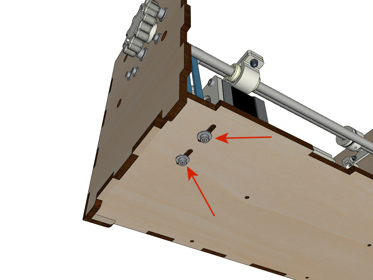
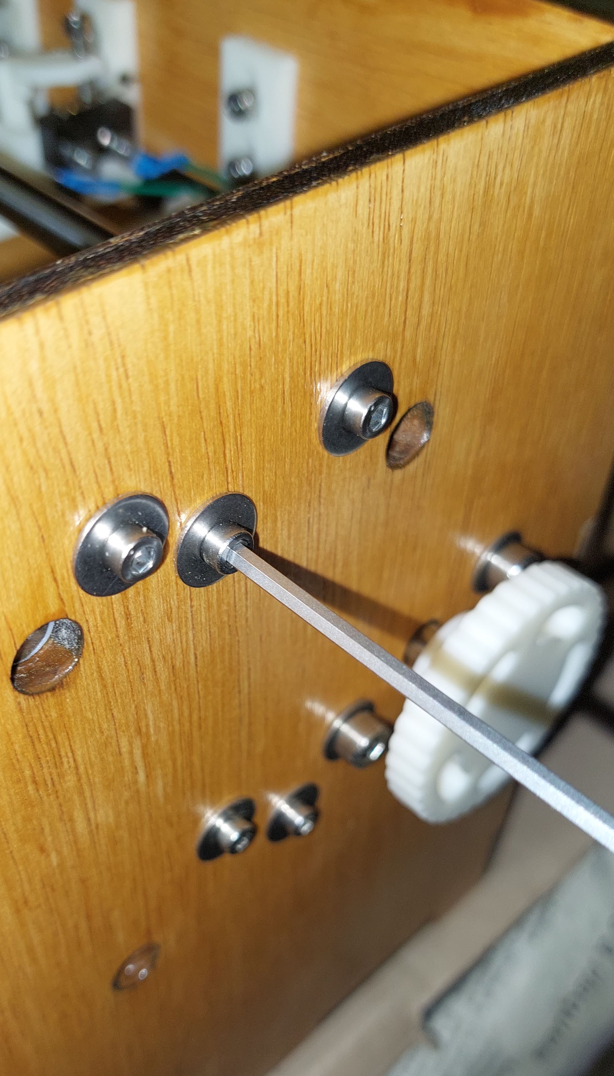
Tighten the 4 axis holder screws on the body (2 on the left side and 2 on the right side) and the 4 grub screws on the axle brackets so that the pins do not slide into their seats.
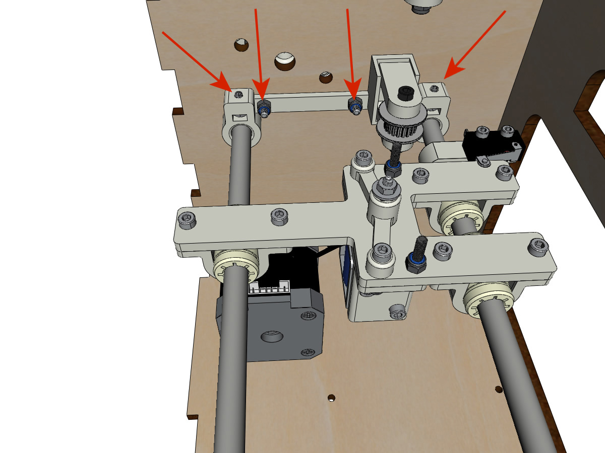
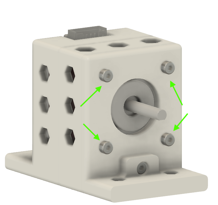
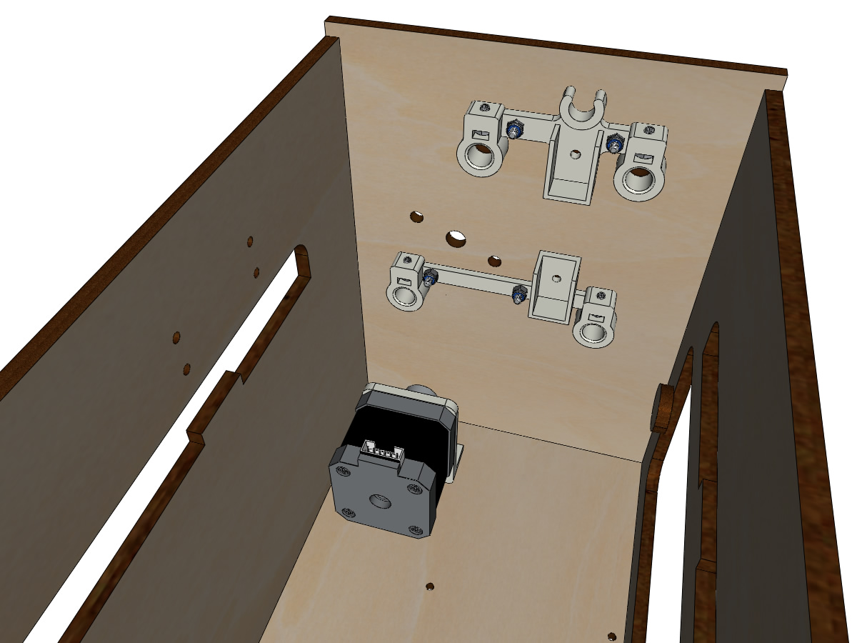
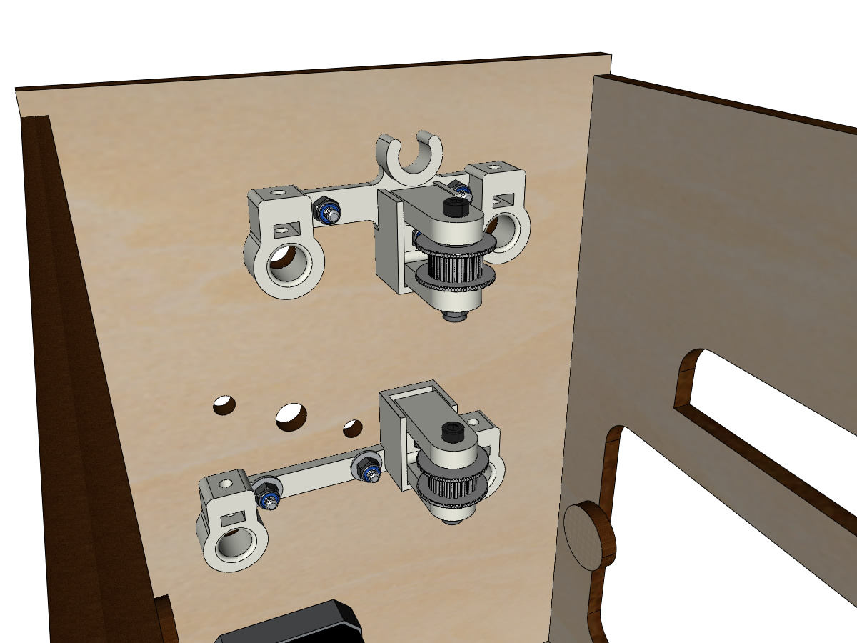
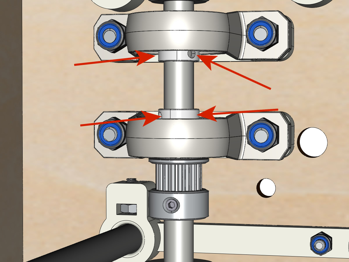
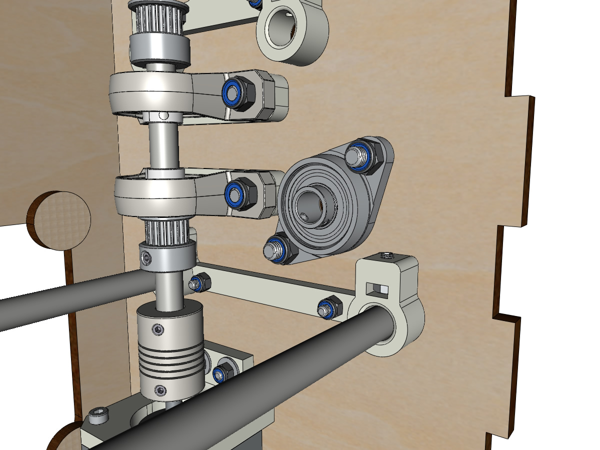
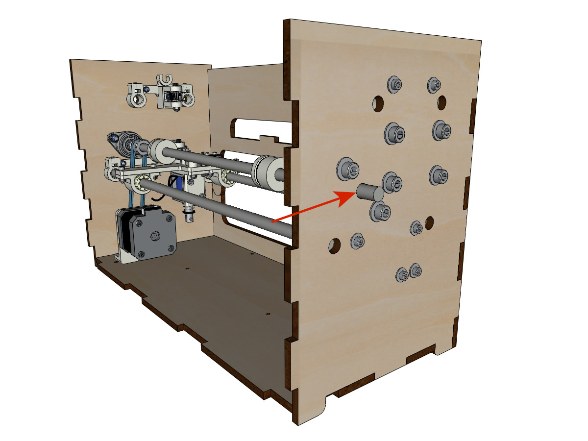
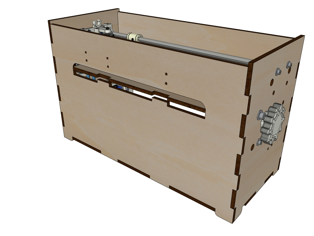
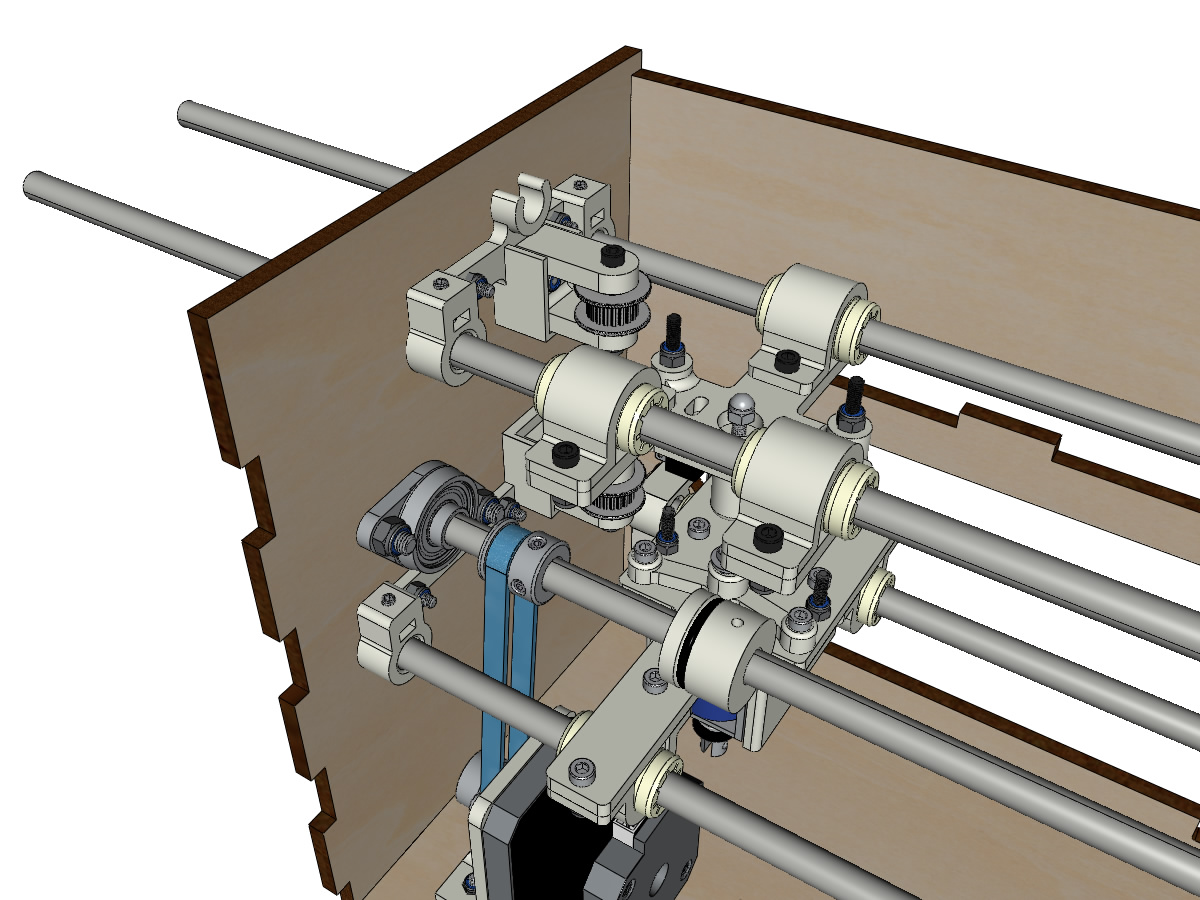
Mounting the vertical axis (step 1)
Equipment:
3D printed parts : 2 X KP08_support
2 KP08
4 M5-25 screw
4 M5 washer
4 M5 nyloc nuts
Note
Before attaching the KP08, make sure the bearings are aligned in their housing. They may be delivered a little misaligned. In this case, insert a Ø 8mm bar and manually actuate it to straighten them.
Screw the KP08_support and the KP08 on the body a bit with the M5-25 screws, M5 washers and M5 NYL nuts.
Observe the position of the KP08 clamping rings.
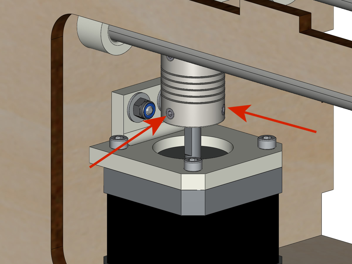
Mounting the vertical axis (step 3)
Equipment:
1 linear shaft Ø 8mm, length : 100mm
1 5*8mm Coupler
Thread the coupler onto the motor shaft (Ø 5mm hole at the bottom).
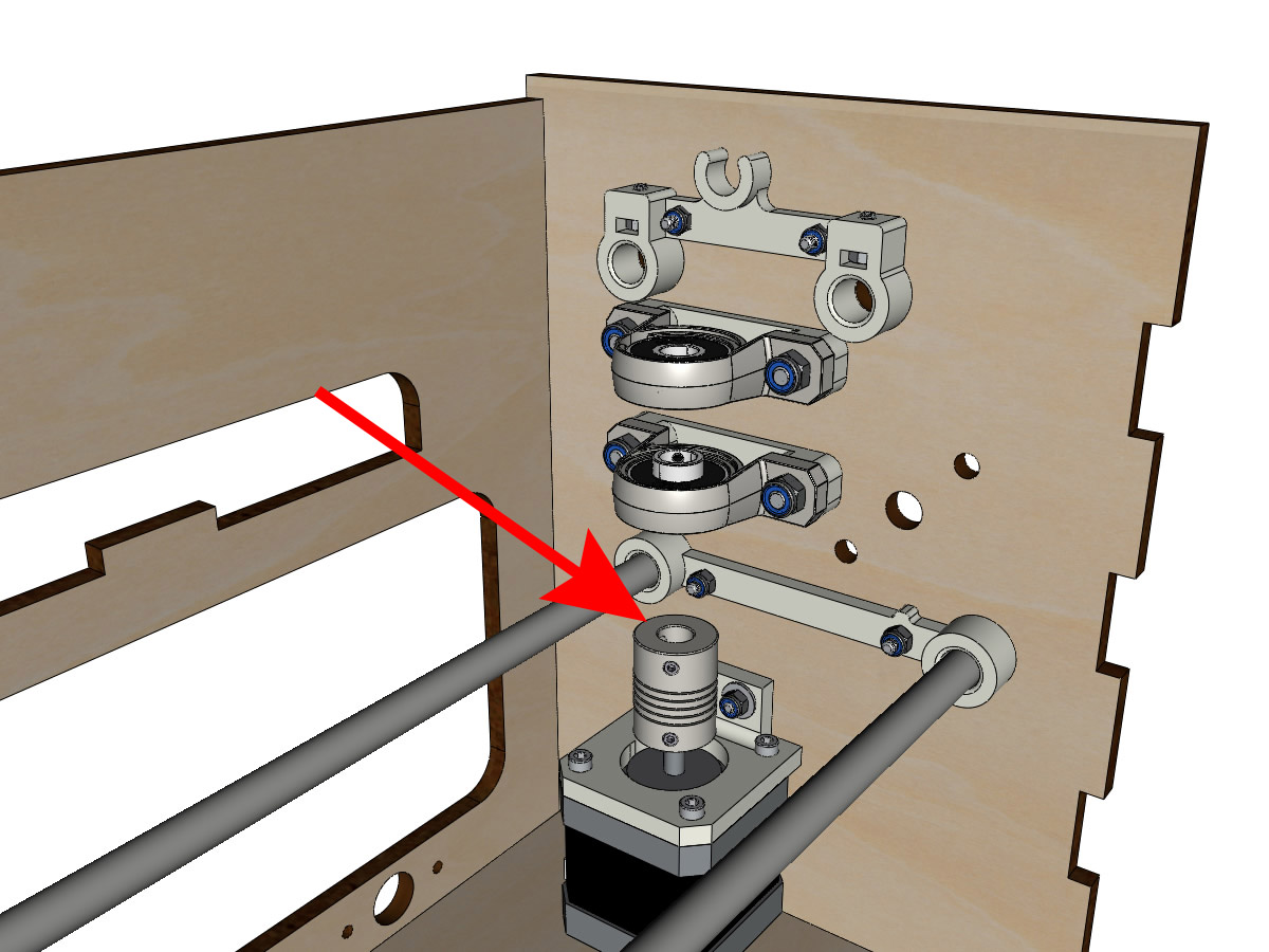
Thread the 100mm linear shaft from the top through the KP08 and into the coupler.
Rotate the linear shaft by hand to ensure that all elements are aligned and that the spindle continues to rotate freely.
The holes of the motor support are oblong and allow to align the motor with the vertical axis in the 2 dimensions.
Screw the first 2 screws of the motor on its support.
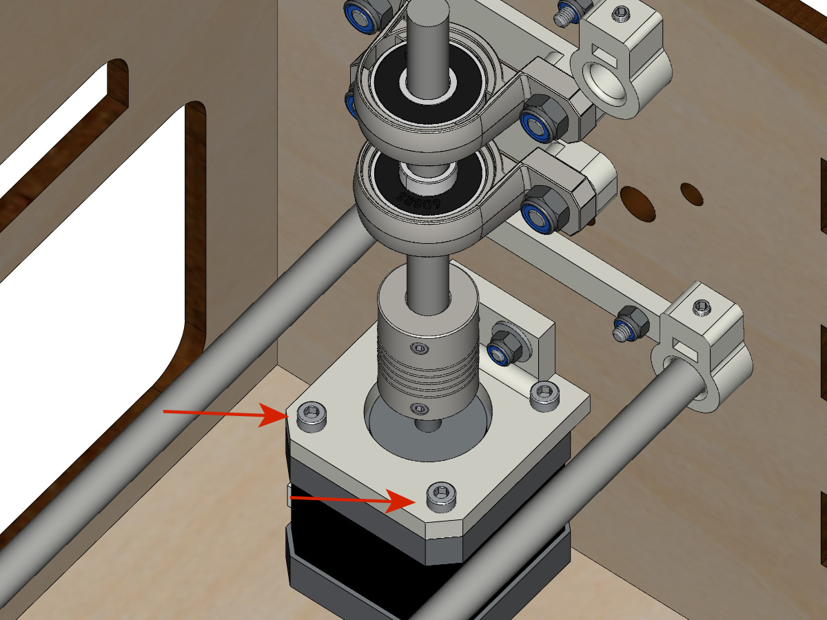
Slowly tighten the KP08 screws by turning the shaft by hand.
Screw the motor support screws onto the body slowly by turning the shaft by hand. ** ADD PICTURE **
Remove the pin and finish screwing the last 2 screws of the motor on its support, then the support on the body.
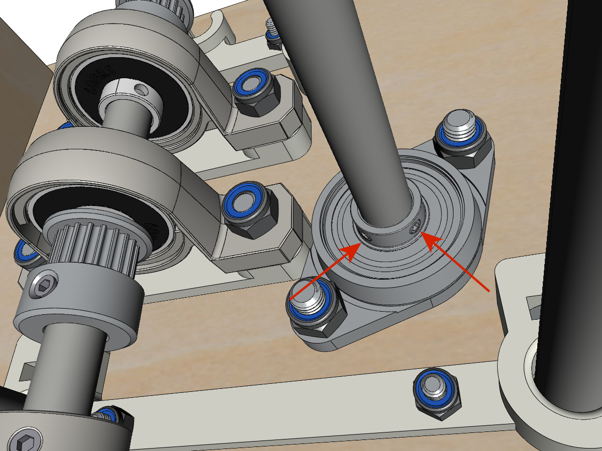
Mount the vertical axis (step 4)
Equipment:
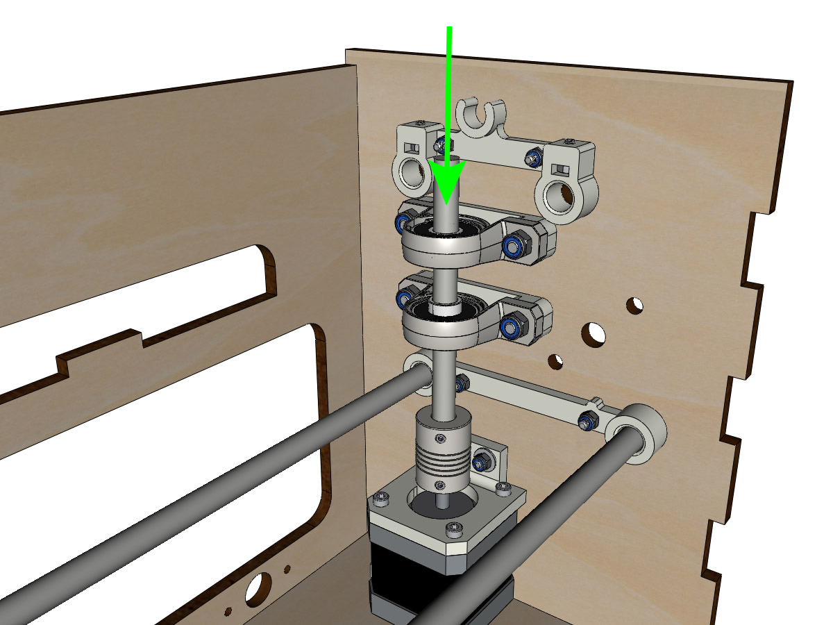
2 pulleys GT2 20 teeth bore 8mm
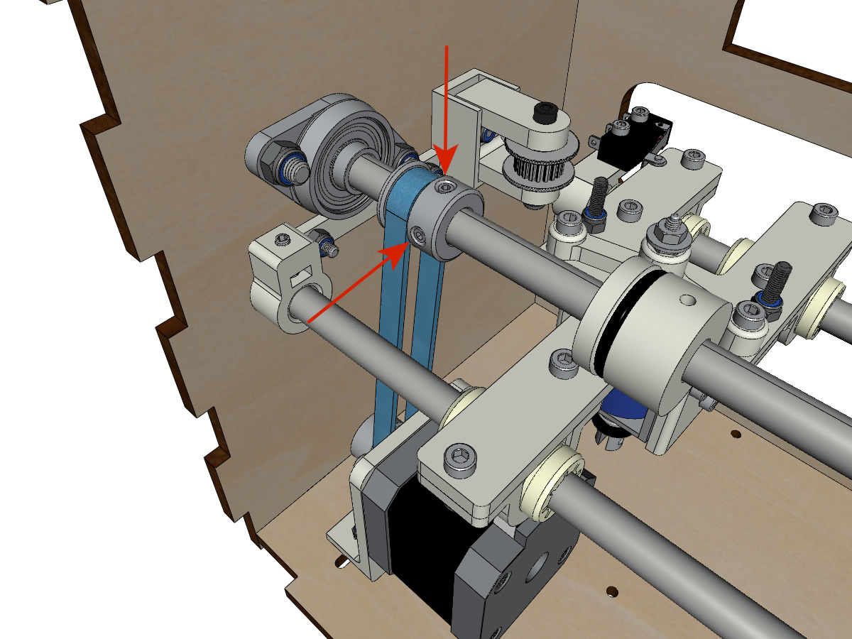
Screw the 2 screws at the bottom of the coupler onto the motor shaft, making sure that one of the screws is in front of the flat part of the motor shaft and that the bottom of the coupler is not resting on the motor.
Thread the 100mm axle into the KP08, the pulleys (respecting their positions) and the coupler.

Screw the 2 screws at the top of the coupler onto the vertical axis.
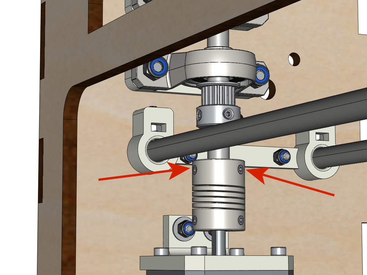
Leave the pulleys free without screwing them onto the axle. They will be screwed when the belt is in place.
Screw the screws of the KP08 clamping rings (2 screws per ring).
Make sure that the axle rotates easily and that the motor does not oscillate. If necessary, loosen the motor and support screws on the body to give them play and re-align.
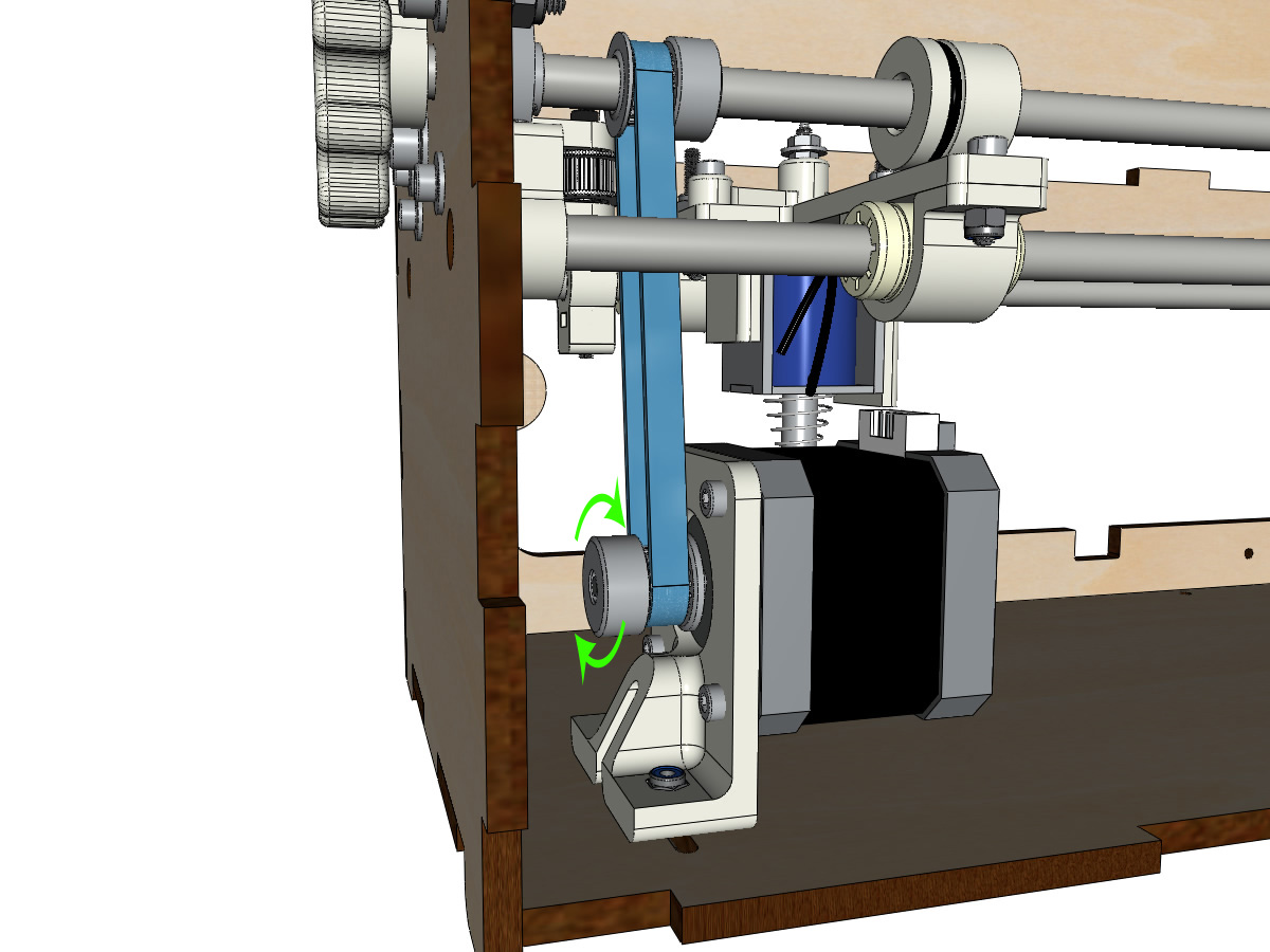
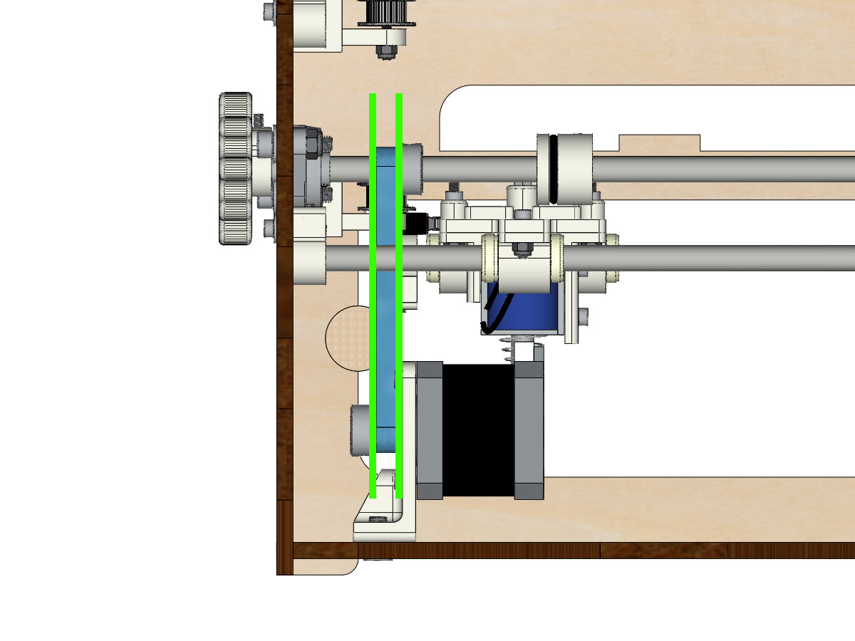
Mounting the low carriage belt
Equipment BrailleRAP:
1 belt GT2 length ± 620mm
2 necklaces
Equipment BrailleRAP XL:
1 belt GT2 length ± 960mm
2 necklaces
Using a collar, attach the strap around the carriage screw with the teeth facing out.
Pass the belt in the free pulley then the pulley of the vertical axis.
Tension the belt while holding the carriage and secure the second end of the belt to its screw with a collar.
Finish stretching the belt with the screw on the outside of the body.
Note
For now, do not tighten the pulley bolts on the axle.
Y axis mounting (step 1)
- Equipment BrailleRAP:
2 KFL8
4 screws M5-18
4 M5 nyloc nuts
4 M5 washer
1 GT2 20 teeth boron 8mm pulley
1 smooth rod Ø 8mm, length: 364mm
1 close belt GT2 length 200 mm
- Equipment BrailleRAP XL:
2 KFL8
4 screws M5-18
4 M5 nyloc nuts
4 M5 washer
1 GT2 20 teeth boron 8mm pulley
1 linear shaft Ø 8mm, length : 505mm
1 close belt GT2 length 200 mm
Fix the KFL8 on the left side with 2 M5-18 screws, 2 M5 washers and 2 M5 NYL nuts.
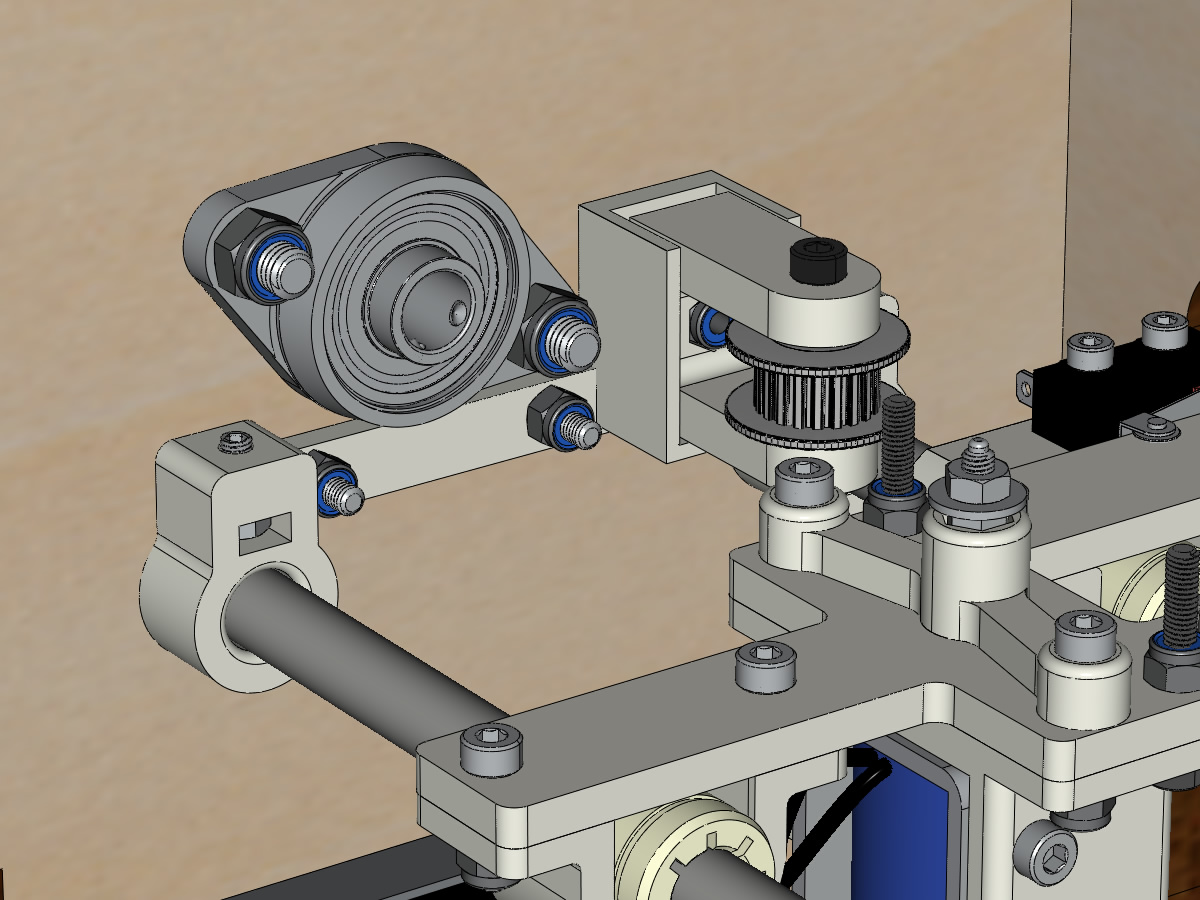
Fix the KFL8 right on the body with the KFL8_support, 2 screws M5-18, 2 washers M5 and the 2 nuts M5 NYL.
Thread the smooth bar halfway through the left side through the body and the KFL8.
In order, thread the GT2 20 tooth boron 8mm pulley, the closed belt and the 3 (A4) or 4 (XL) ROLL_joint3 (pay attention to the position of the O-ring). Put the belt closed on the pulley of motor Y and on the pulley of the axle.
Press the axle into the right KFL8 and cross it so that it protrudes ± 12mm from the body.
Tighten the screws of the KFL8 rings.
Mounting the Y axis (step 2)
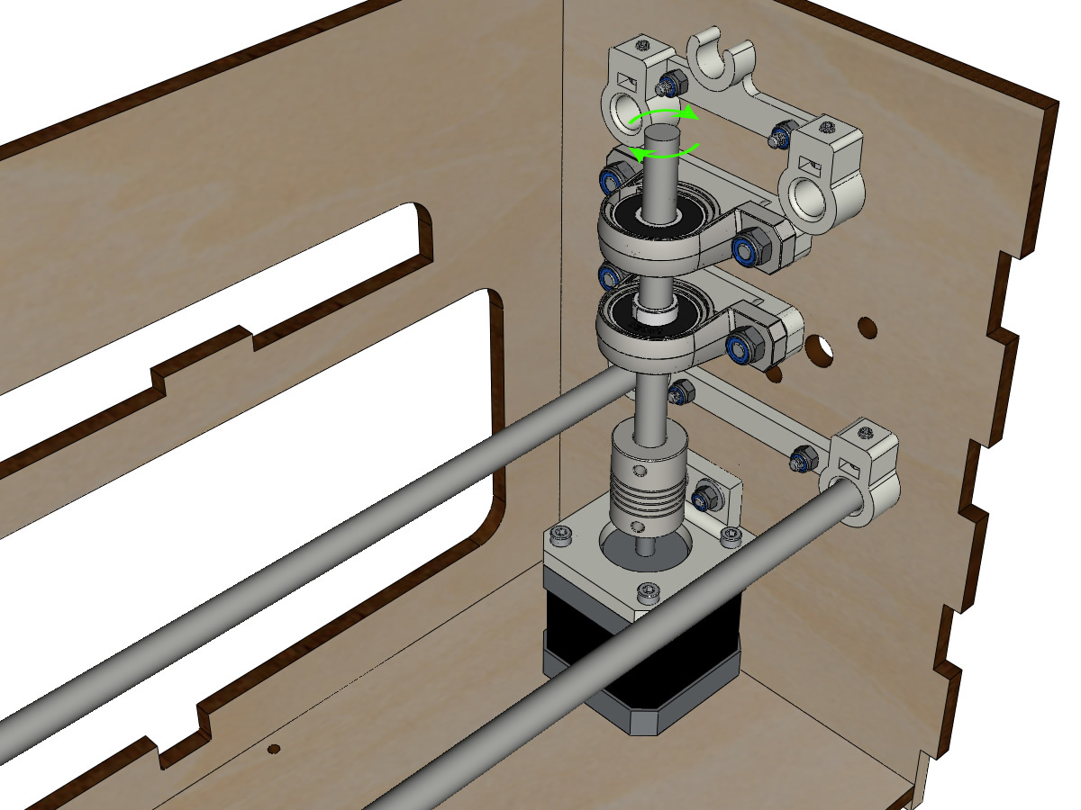
Rotate the motor pulley by hand so that the pulley on the shaft aligns vertically with the motor pulley.
Move the Y motor / support assembly along the oblong holes under the body to tension the closed belt and tighten the 2 screws.
Tighten the 2 screws of the pulley of the axle.
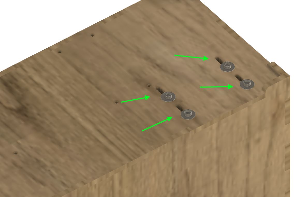
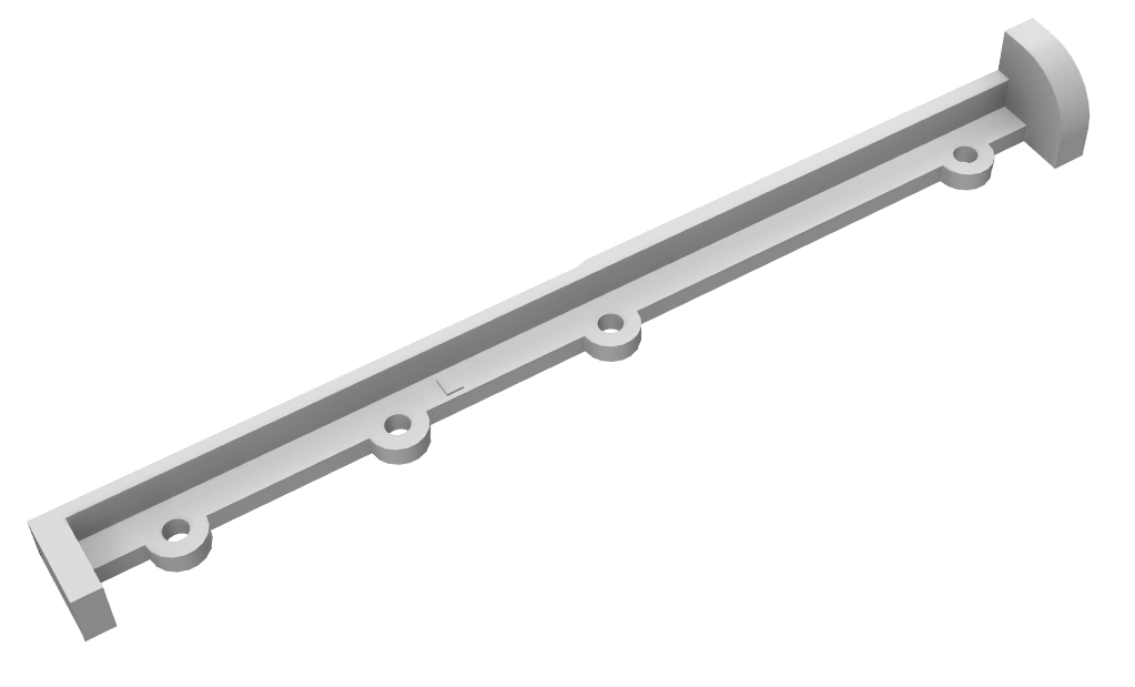
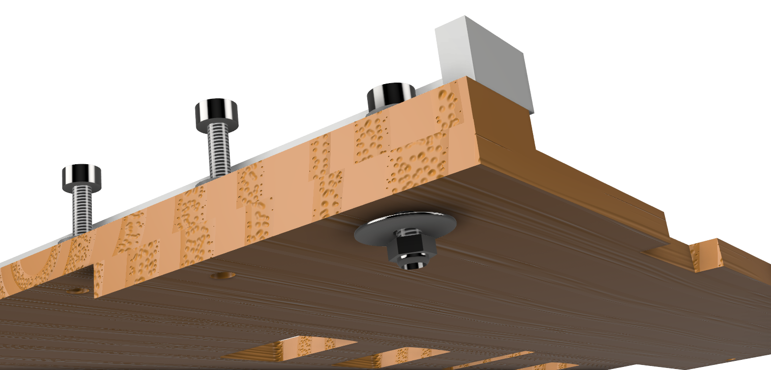
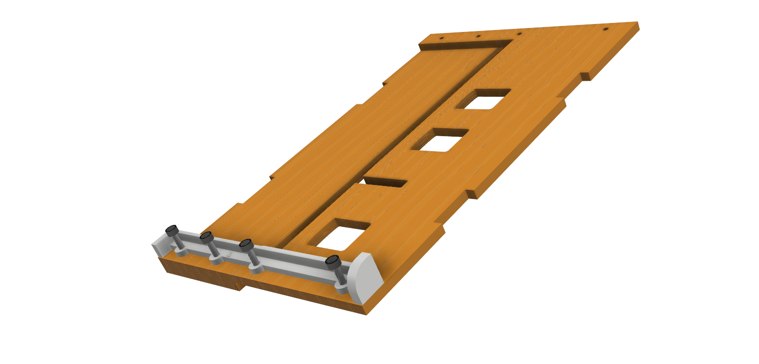
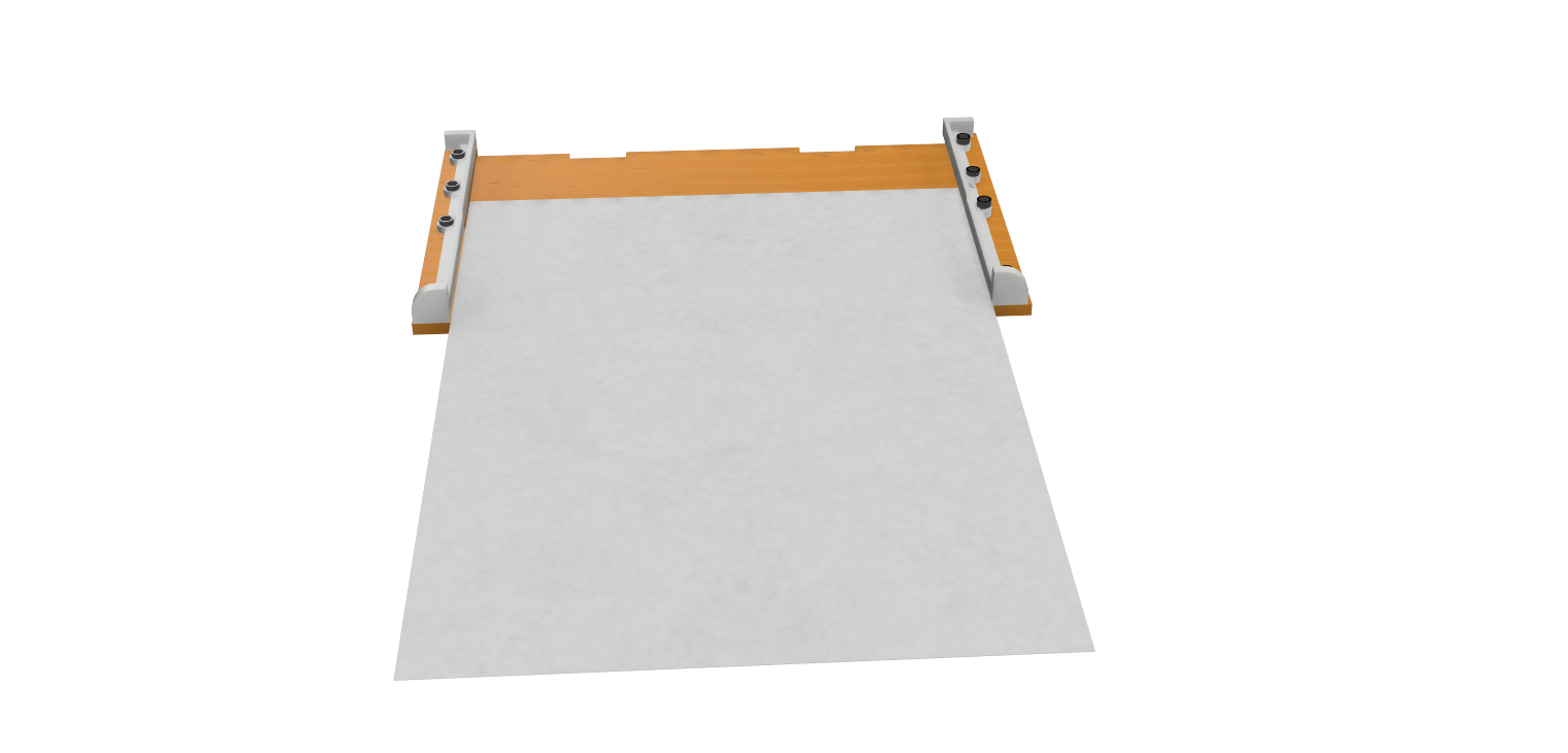
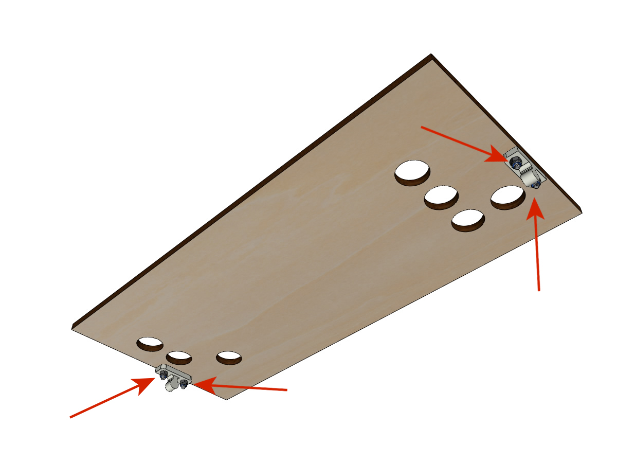
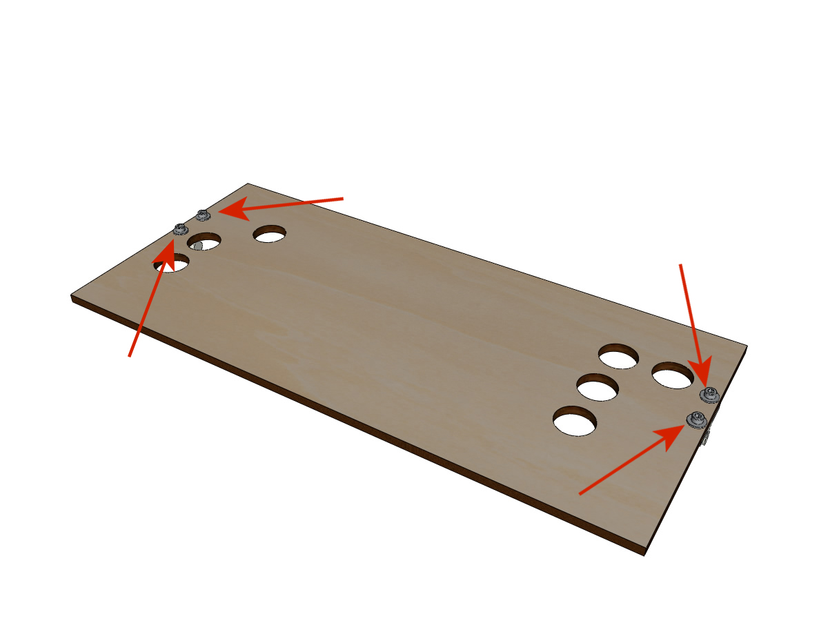
Assembling paper guides on the plate
Equipment:
3D printed parts: PAPER_GUIDE_left for BrailleRAP
3D printed parts : PAPER_GUIDE_right for BrailleRAP
3D printed parts: paper_guide_left_XL for BrailleRAP XL
3D printed parts : paper_guide_right_XL for BrailleRAP XL
PAPER_support (laser cut 5mm plywood)
4 M3-16 screws
4 M3-14 screws
8 wide M3 washers
8 M3 nyloc nuts
Note
M3-16 screws (M3-18 if you don’t have M3_16) are used for the holes where there are 2 thicknesses of wood.
Note
C’est à cette étape que ce trouve la principale difference entre une BrailleRAP et une BrailleRAP XL.
BrailleRAP use part PAPER_GUIDE_left et PAPER_GUIDE_right.
BrailleRAP XL use parts paper_guide_left_XL and paper_guide_right_XL.
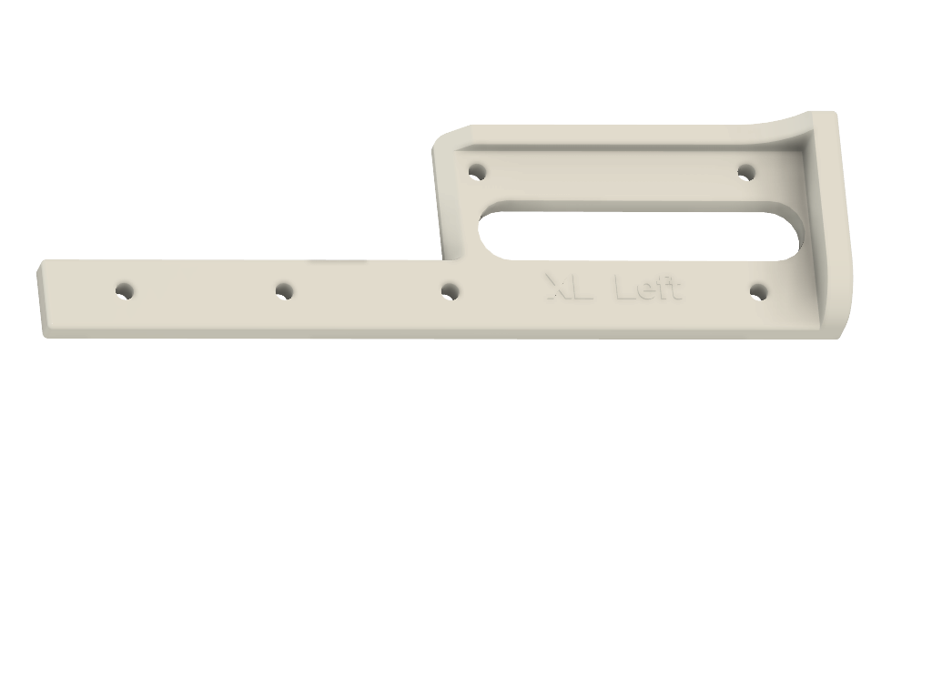
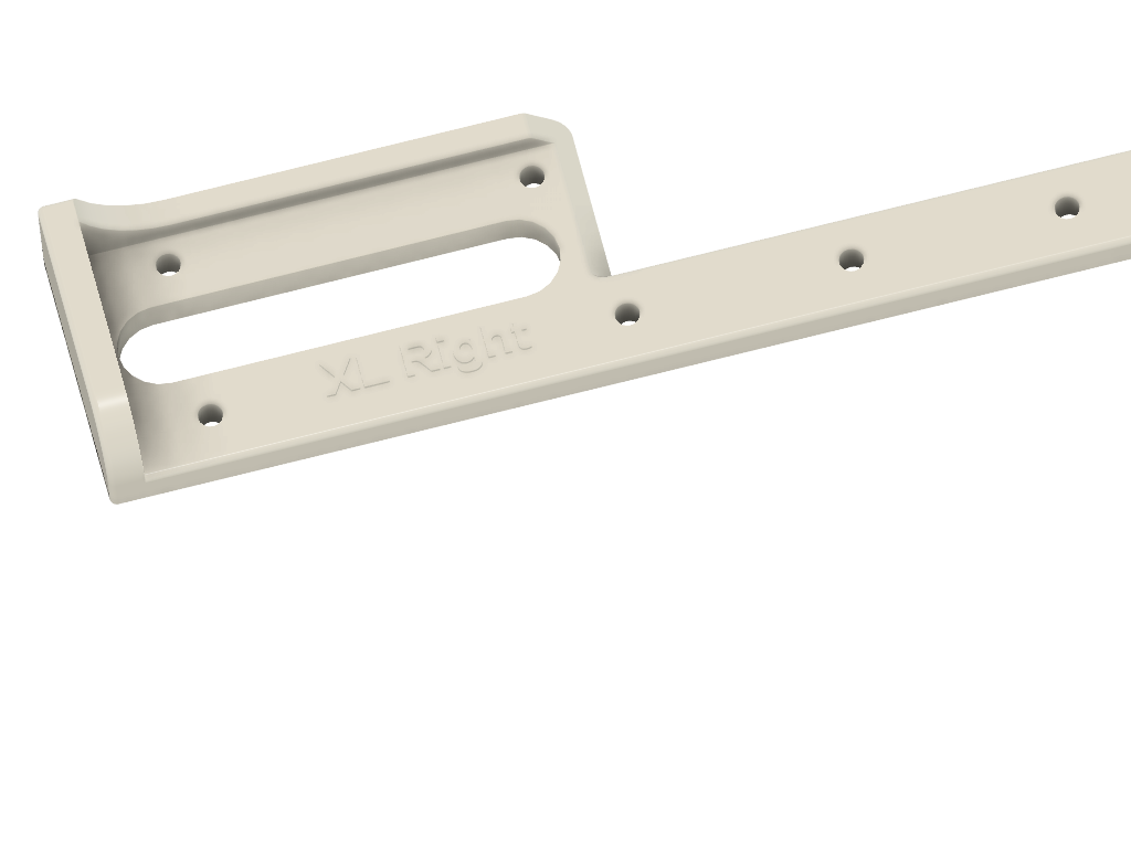
Left part.
Assemble the paper guides on the plate with the M3-16 screws and M3 NYL nuts.
Repeat the operation for the right side.
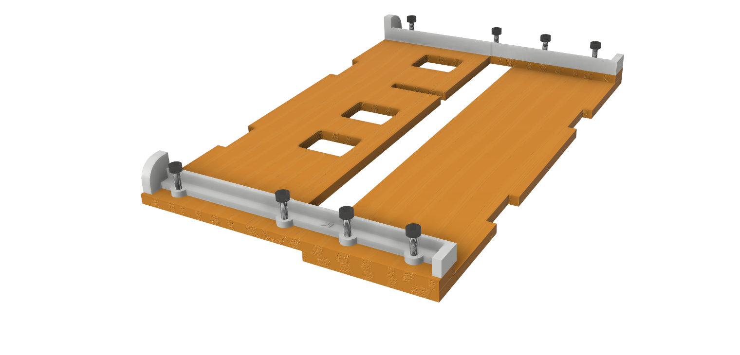
Check that you can put a sheet of paper on the tray without that the sheet warps. If the sheet warps, try to remove the paper guides before clamping.
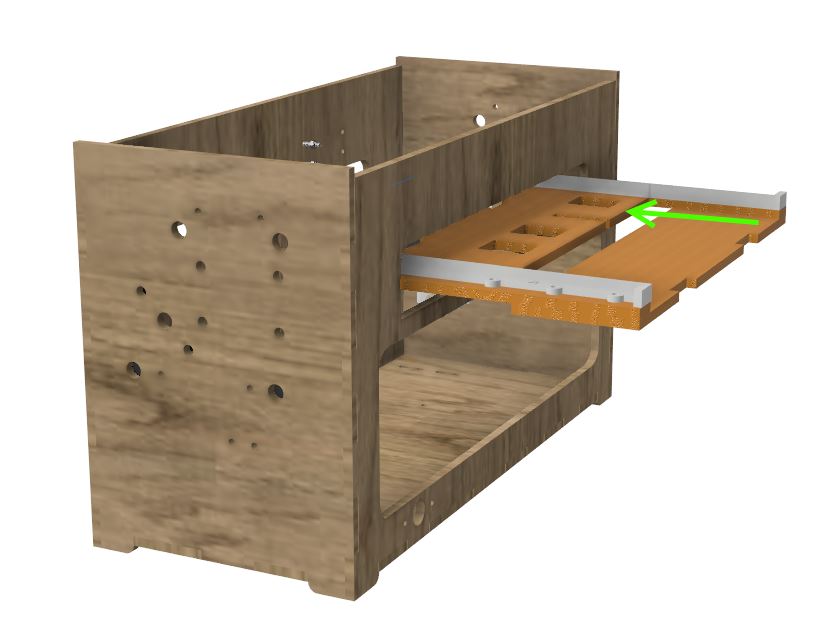
Bonding of the paper plate
Equipment:
PAPER_support (laser cut 5mm plywood).
3 Prepared paper rolls (with gasket and screws) (4 for BrailleRAP XL)
Note
Glue the plate only if you are sure of the mounting that is in below. If you’re not sure, you can just position the support plate, you will bond it at the end when The embosser will work.
Glue the notches that will be in contact. Insert the plate from the front and hold it firmly with tape during the drying time.
Mounting the top cart (step 2)
Equipment BrailleRAP:
2 smooth bars Ø 8mm, length: 330mm
Equipment BrailleRAP XL:
2 smooth bars Ø 8mm, length: 470mm
Push the bars halfway through the outside of the frame.
Thread the top trolley over the rods.
Finish putting on the bars.
Note
The edge of the wood should remain visible.
Tighten the axle holder screws on the body on the left and right.
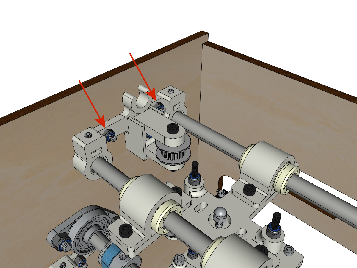
Screw the grub screws of the axle supports on the left and right.

Laying the trolley strap up
Equipment BrailleRAP:
1 belt GT2 length ± 620mm
2 necklaces
Equipment BrailleRAP XL:
1 belt GT2 length ± 620mm
2 necklaces
Using a collar, attach the strap around the carriage screw with the teeth facing out.
Pass the belt in the free pulley then the pulley of the vertical axis.
Tension the belt while holding the carriage and secure the second end of the belt to its screw with a collar.
Finish stretching the belt with the screw on the outside of the body.
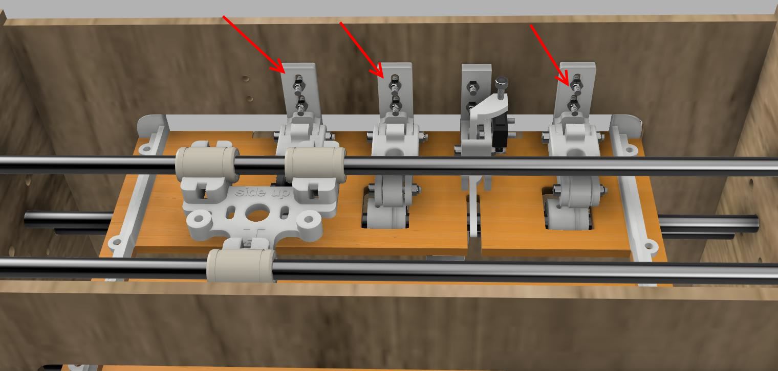
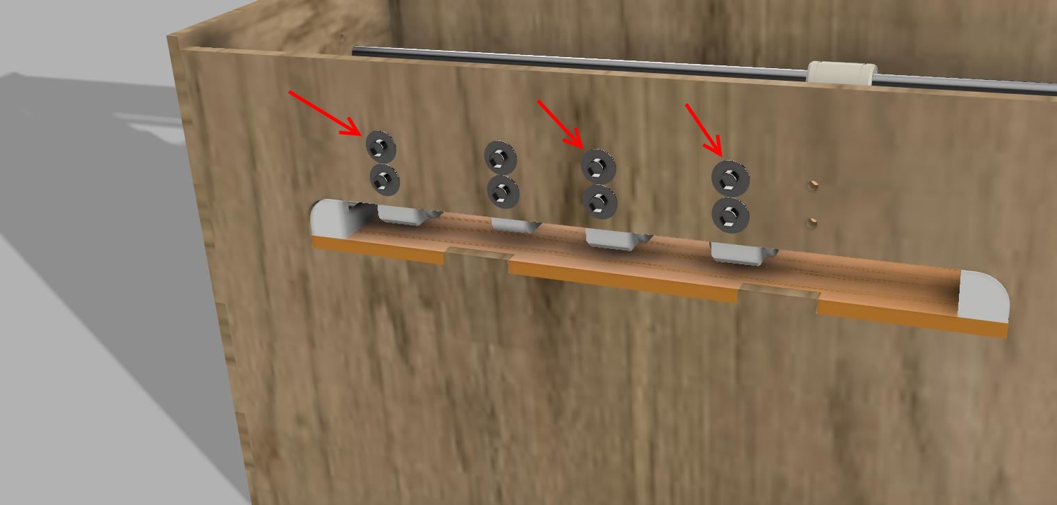
Assembly of the paperweights (step 2):
Equipment BrailleRAP:
3 CLIPBOARD mounted in step 1
6 screws M3-14
6 wide M3 washers
6 M3 nyloc nuts
Equipment BrailleRAP XL:
4 CLIPBOARD mounted in step 1
8 screws M3-14
8 wide M3 washers
8 M3 nyloc nuts
Note
The oblong holes in the printed parts adjust the pressure of the CLIPBOARD on the paper.
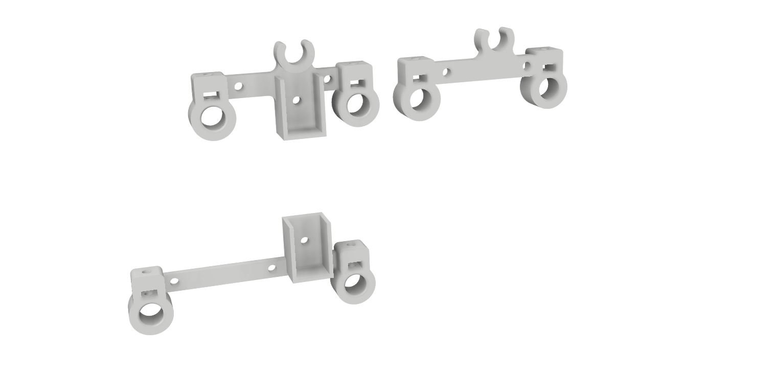
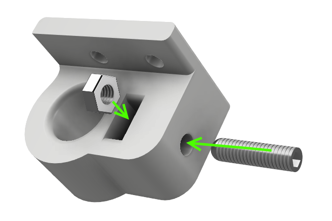
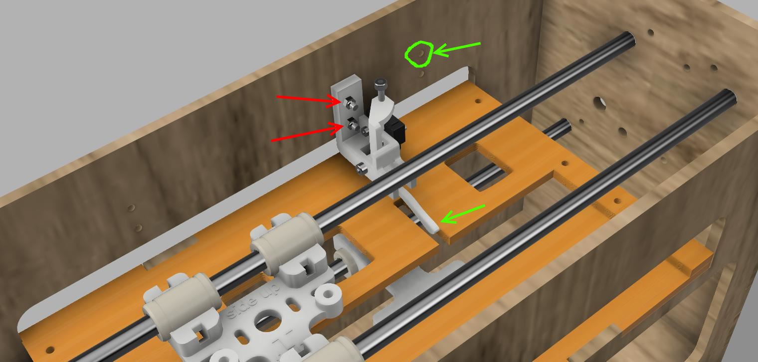
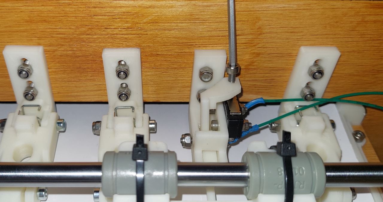
Assembly of the Y limit switch
Equipment:
3D printed part(s): ENDSTOP_Y_support, ENDSTOP_Y_lever_weight
2 M3-14 screws
2 M3-12 screws
1 M3-20 screw
2 wide M3 washers
3 M3 nyloc nuts
2 M3 nuts
1 endstop switch
2 M2.5-14 screws
2 M2.5 nyloc nuts
Note
It’s better to use an endstop with angled wire.
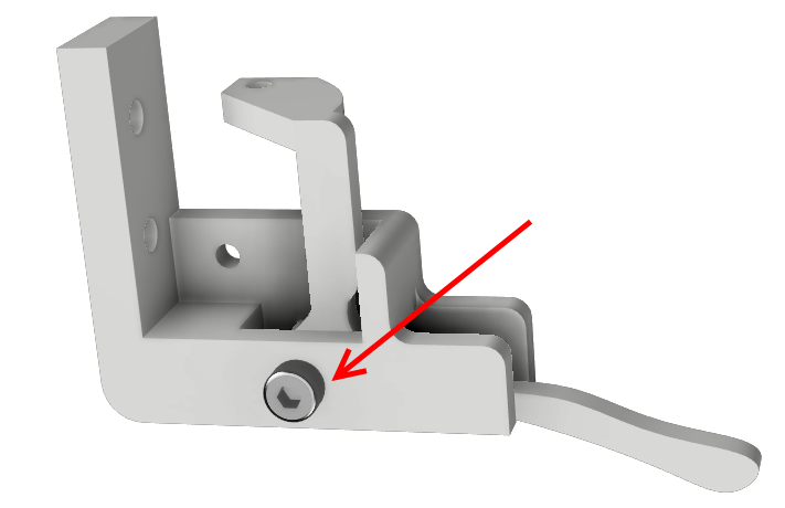
Tap the adjustment screw support with an M3 tap
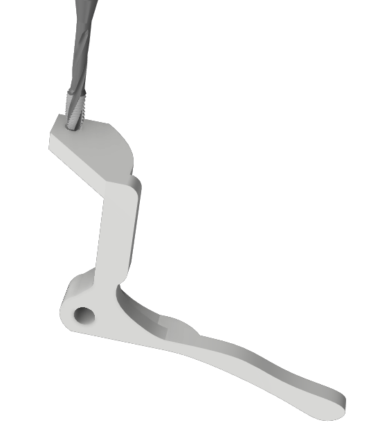
Position the lever ENDSTOP_Y_LEVER in the support ENDSTOP_Y_support.
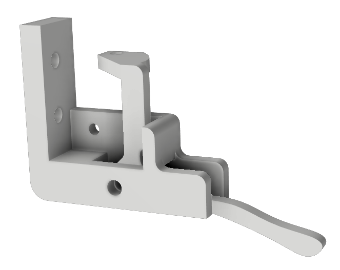
Fix the lever ENDSTOP_Y_LEVER to the support ENDSTOP_Y_support with an M3-20 screw and an M3-NYL nut
Note
Do not tighten the M3 nut, the lever must be able to rotate freely in his support.
Assemble the limit switch and the ENDSTOP_Y_support using M2.5-14 screws and M2.5 NYL nuts.
Position the M3-12 adjustment screw on the lever ENDSTOP_Y_LEVER_weight
Add an M3-NYL nut , 2 M3 nuts and an M3-12 screw on the lever ENDSTOP_Y_LEVER_weight
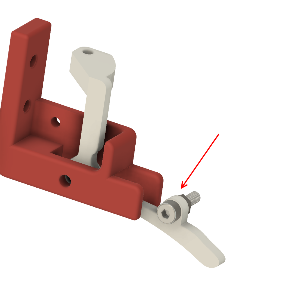
Assemble the limit switch assembly and the ENDSTOP_Y_support to the body using the M3-14 screws, M3 washers and M3 NYL nuts.
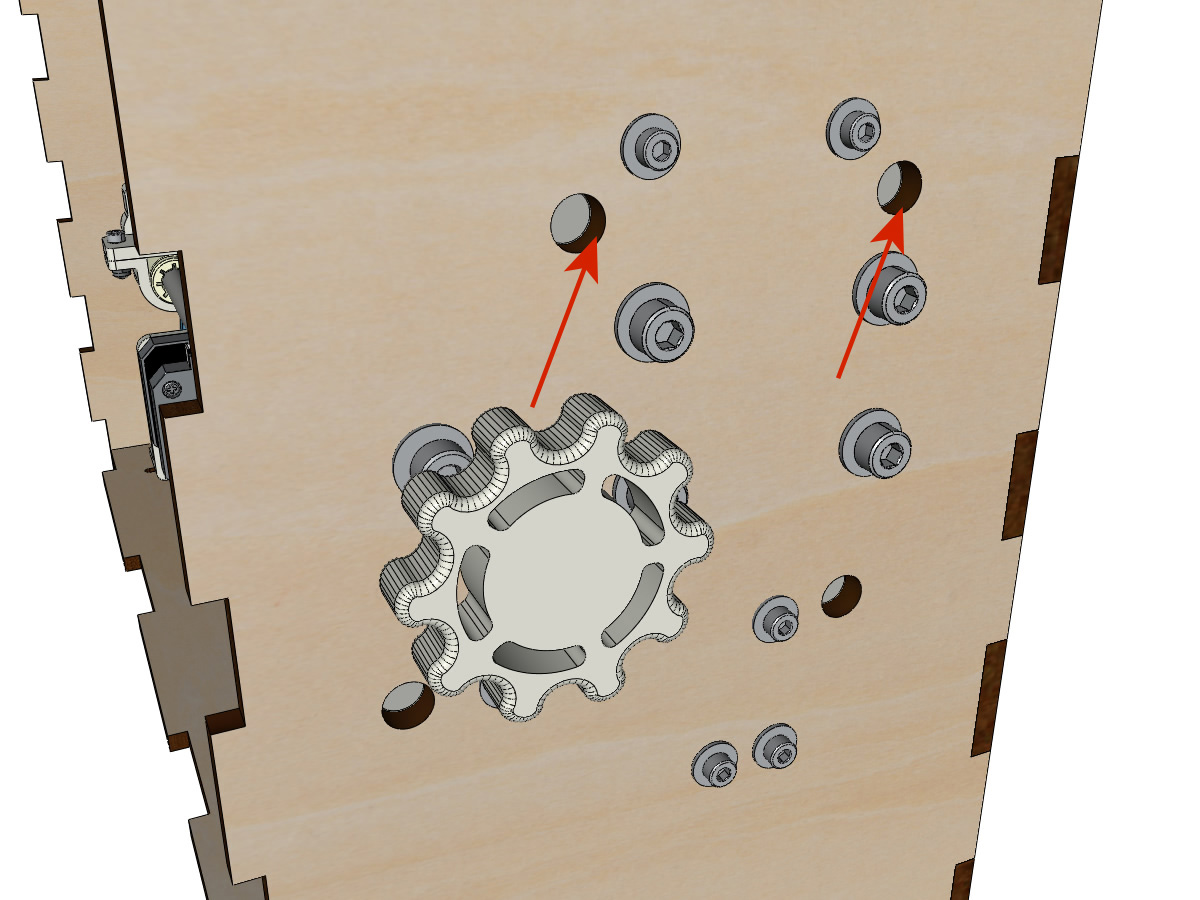
Fixing the clips on the lid
Equipment:
3D printed parts: 2 LID_LOCK
4 M3-14 screws
4 M3 nyloc nuts
Assemble the 2 LID_LOCK on the cover using the M3-14 screws, M3 washers and M3 NYL nuts.
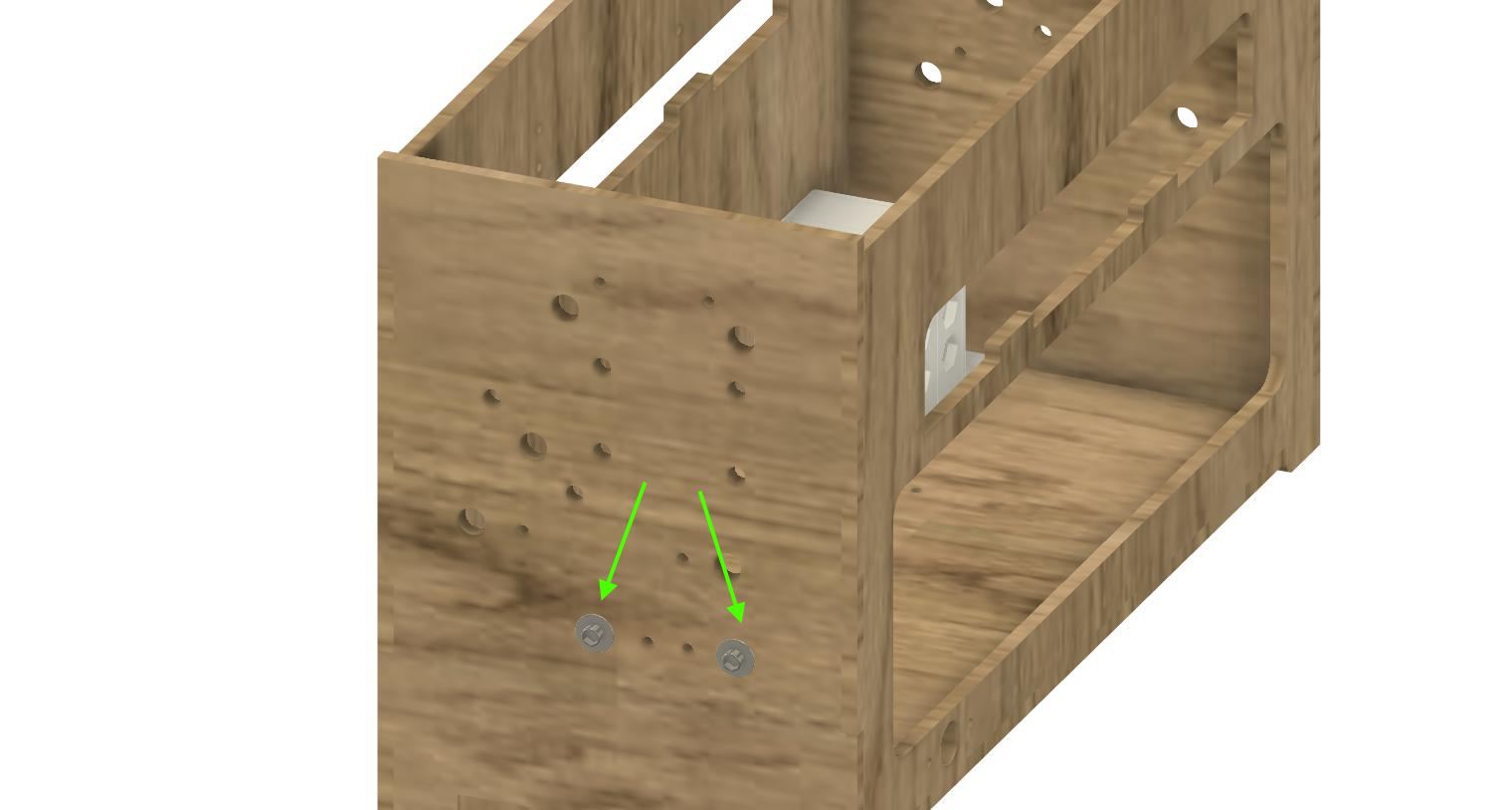
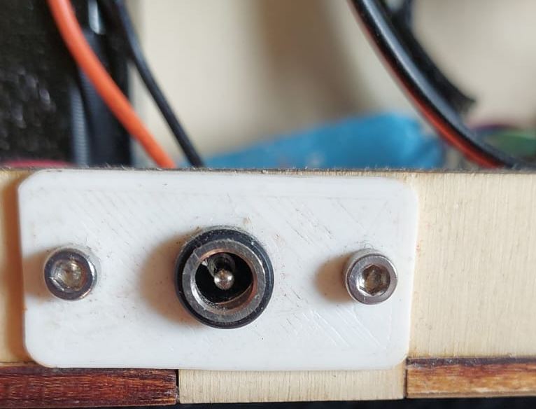
Fixing the plate for the power supply base
Equipment:
3D printed part: POWER_plate
2 M3-14 screws
2 M3 nyloc nuts
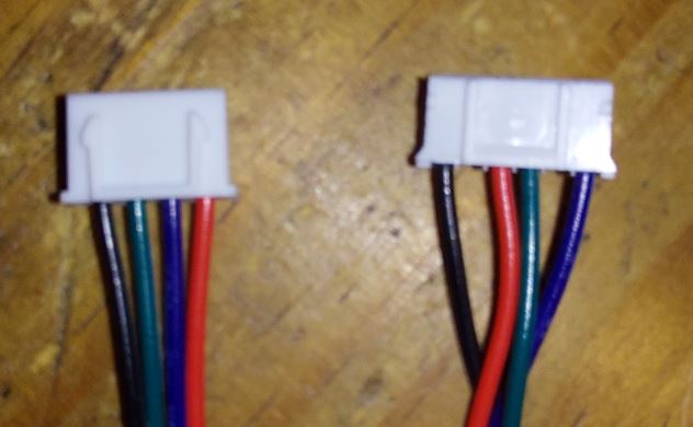
Motor wires setup
2 XH 2.54 4pins => 6pins stepper motor cable
Check cable wiring. Wiring follow
board side |
motor side |
|---|---|
1 |
1 |
2 |
4 |
3 |
6 |
4 |
3 |
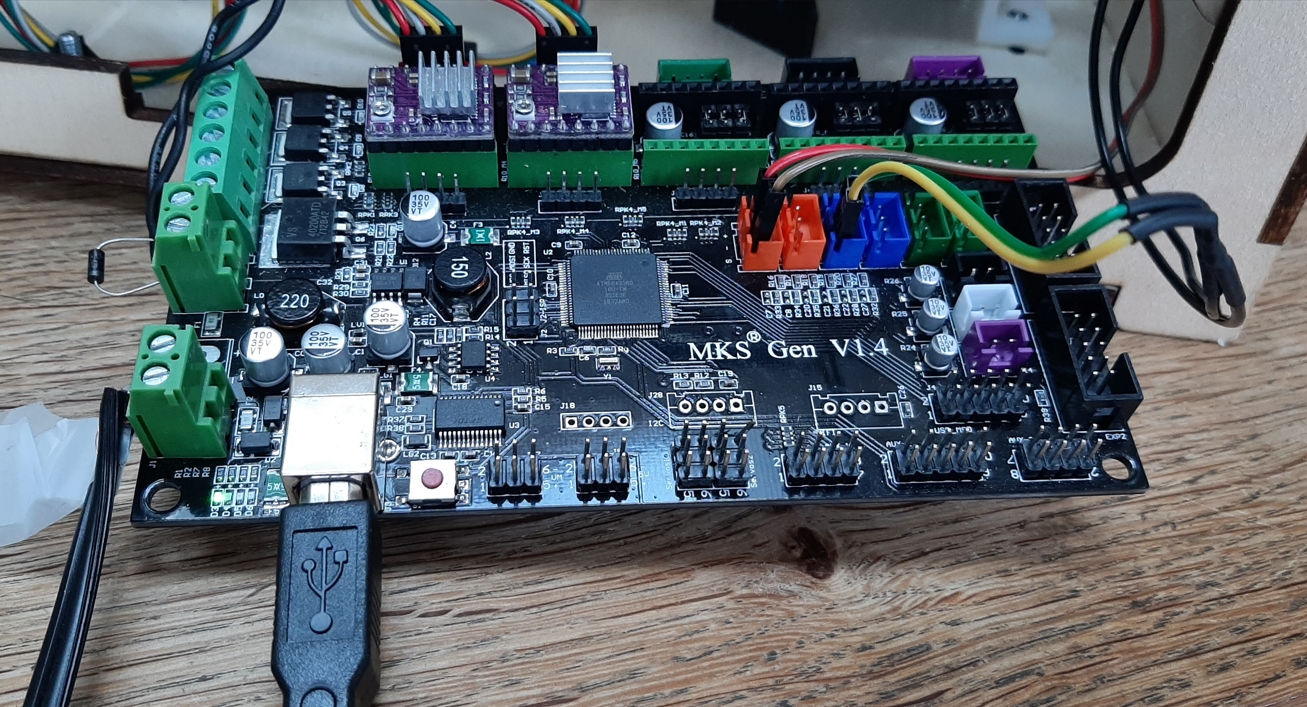
Electronic board controller mount MKS 1.4
Equipment:
MKS GEN 1.4 card
4 spacer M3-12
4 wide M3 washers
8 screw M3-8
Assemble the 4 spacers on the card.
Note
To be able to carry out the final adjustments easily, we recommend wiring the card outside the chassis. Once the embosser is functional, you can mount the board in the embosser.
Electronic board wiring for MKS 1.4
General diagram:
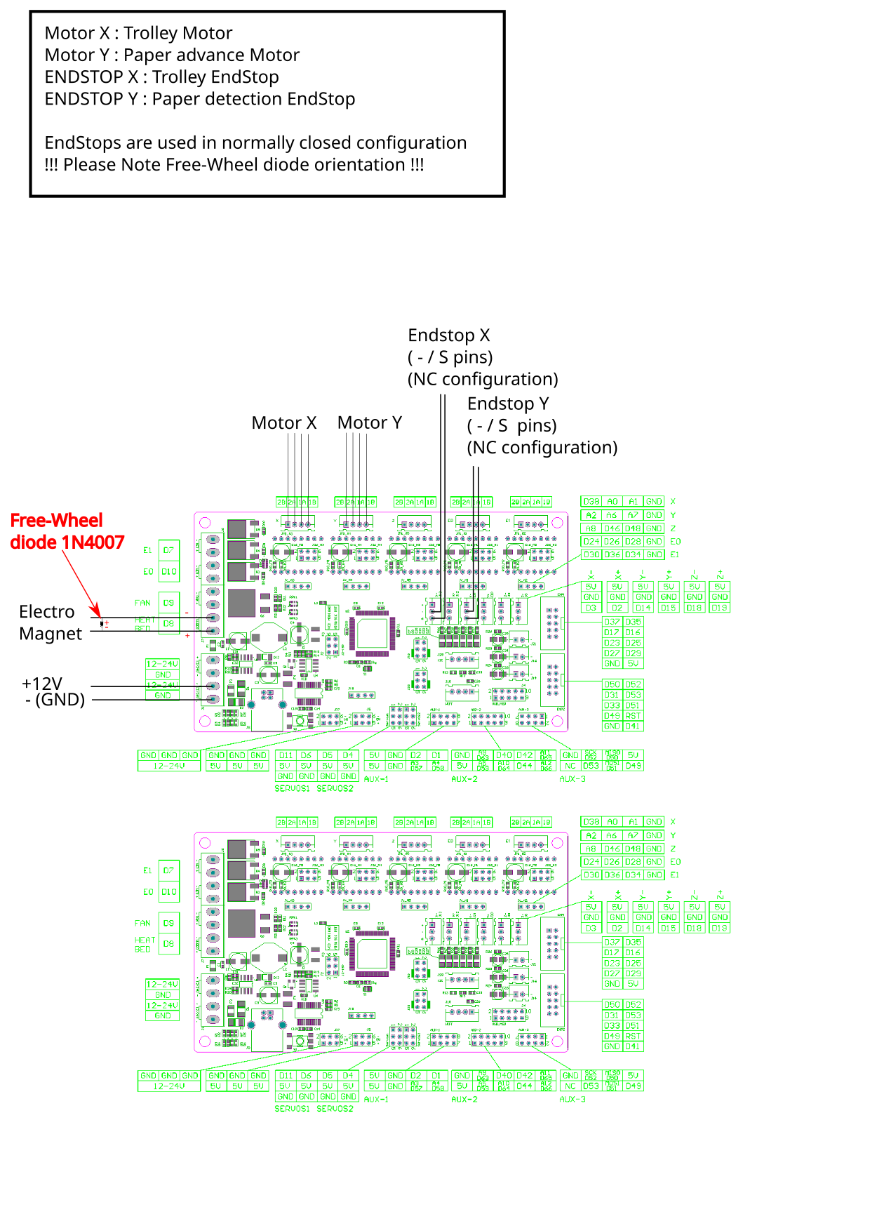
Photo of the assembled board
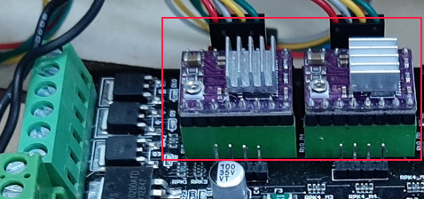
Laying the drivers on the electronic board
Equipment:
MKS GEN 1.4 card
2 DRV8825 drivers
6 jumpers
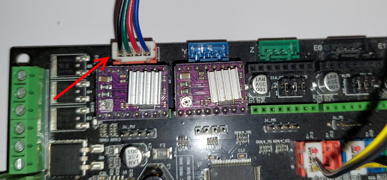
If the card is not supplied already equipped with jumpers, put in the places of the drivers of engines X and Y.
Push the drivers into X and Y slots.
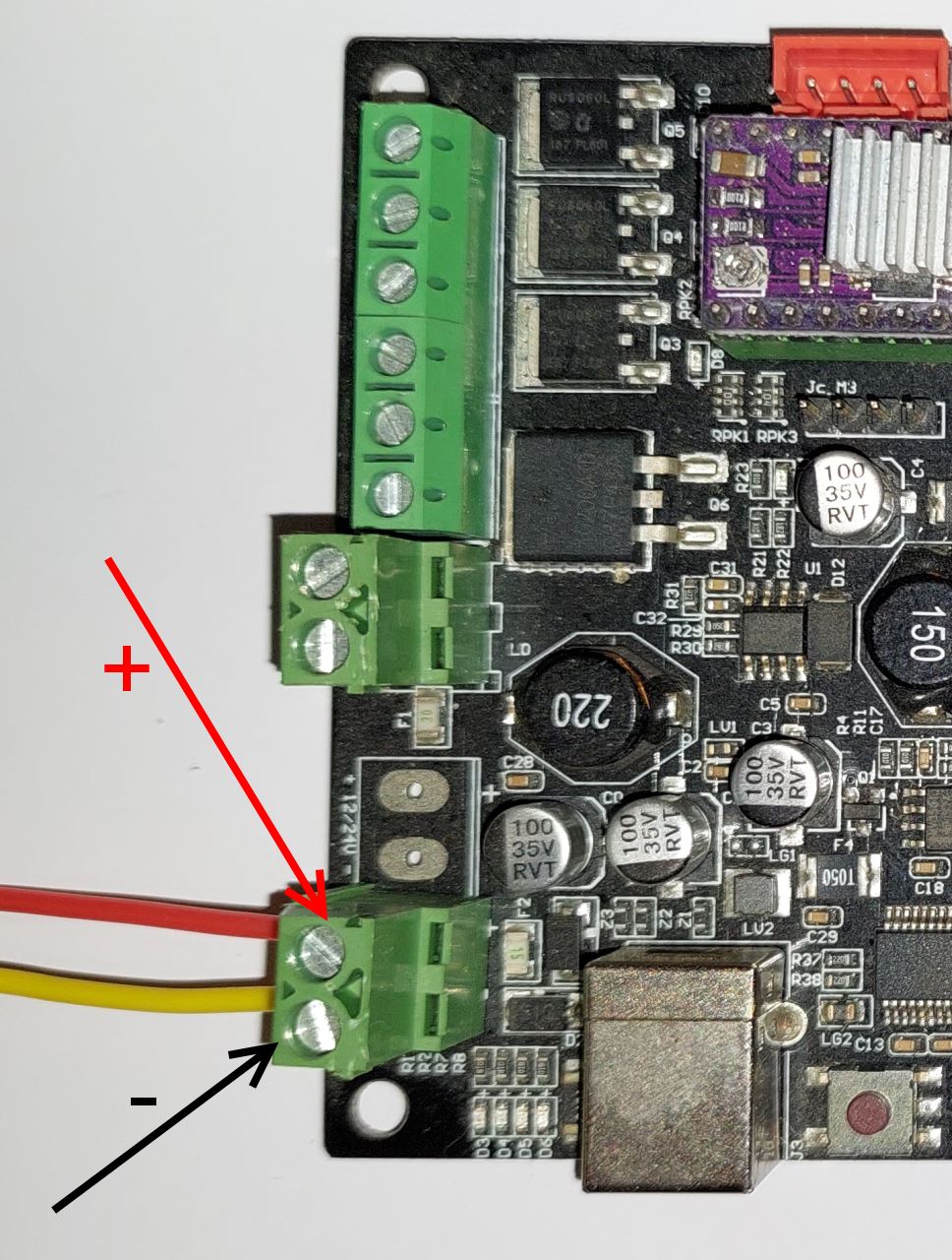
12V power wiring
place the 2 wires coming from the POWER_plate socket in the terminal block of the MKS board
Adjusting motor drivers
Note
This step must IMPERATIVELY be carried out before wiringengines.
Check that you can connect the 12V power supply to the board (a last check to avoid sparks is better :-) )
Connect the 12 V power supply to the board.
for each driver, measure, with a multimeter, the voltage between the adjustment potentiometer and mass of the USB connection.
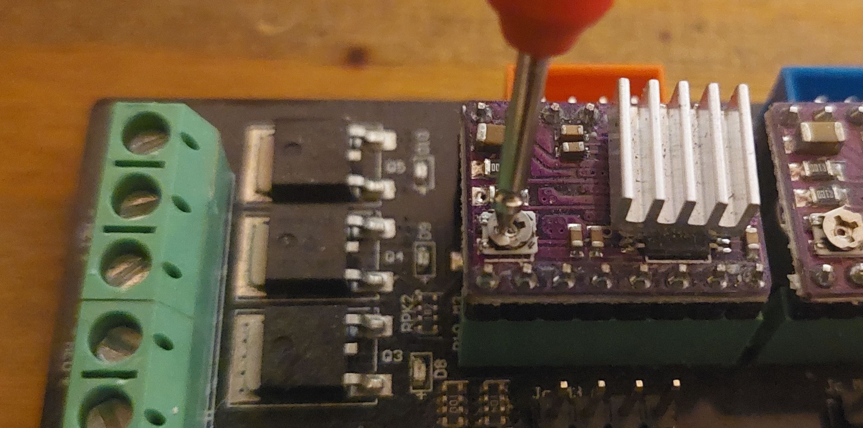
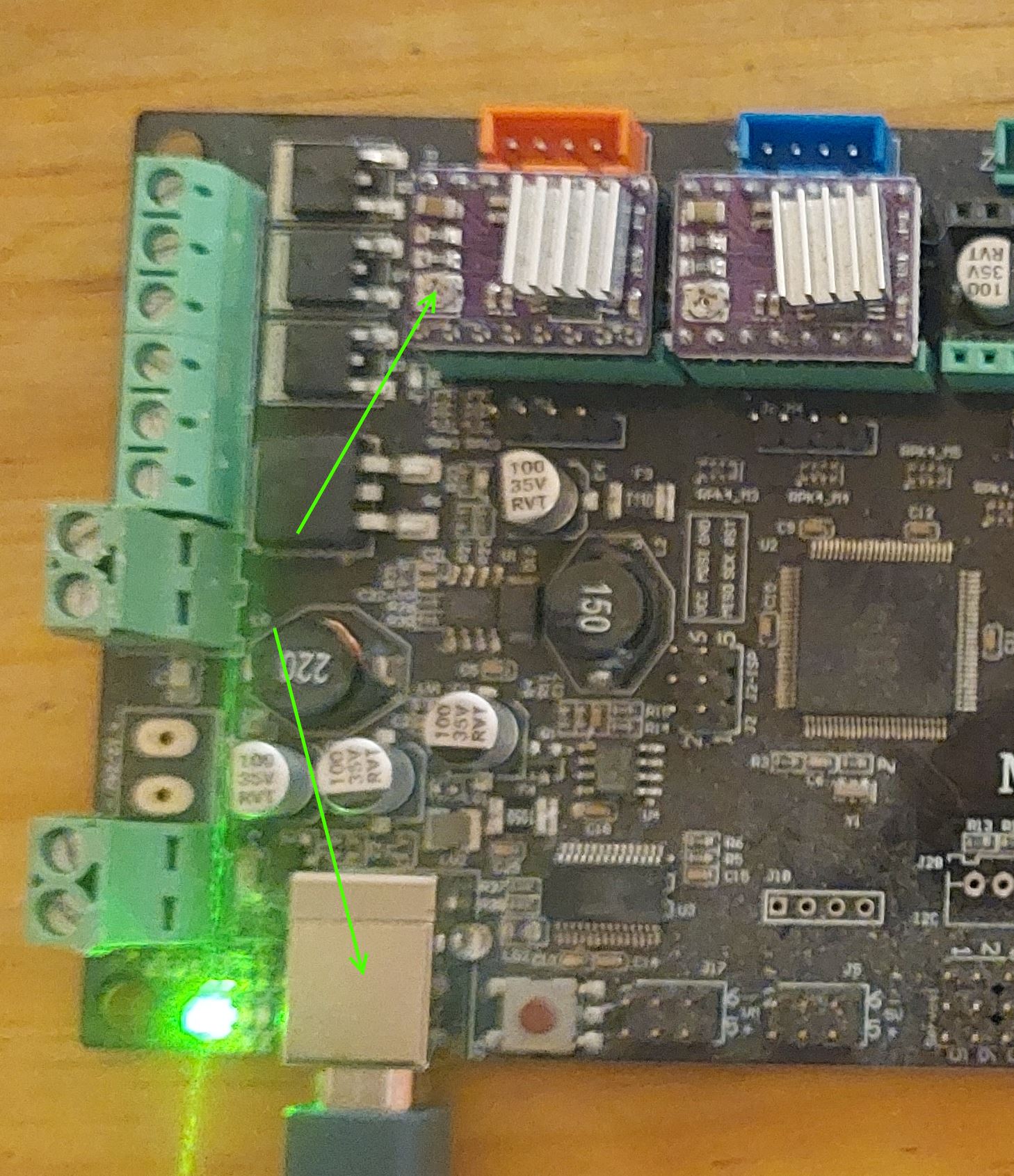
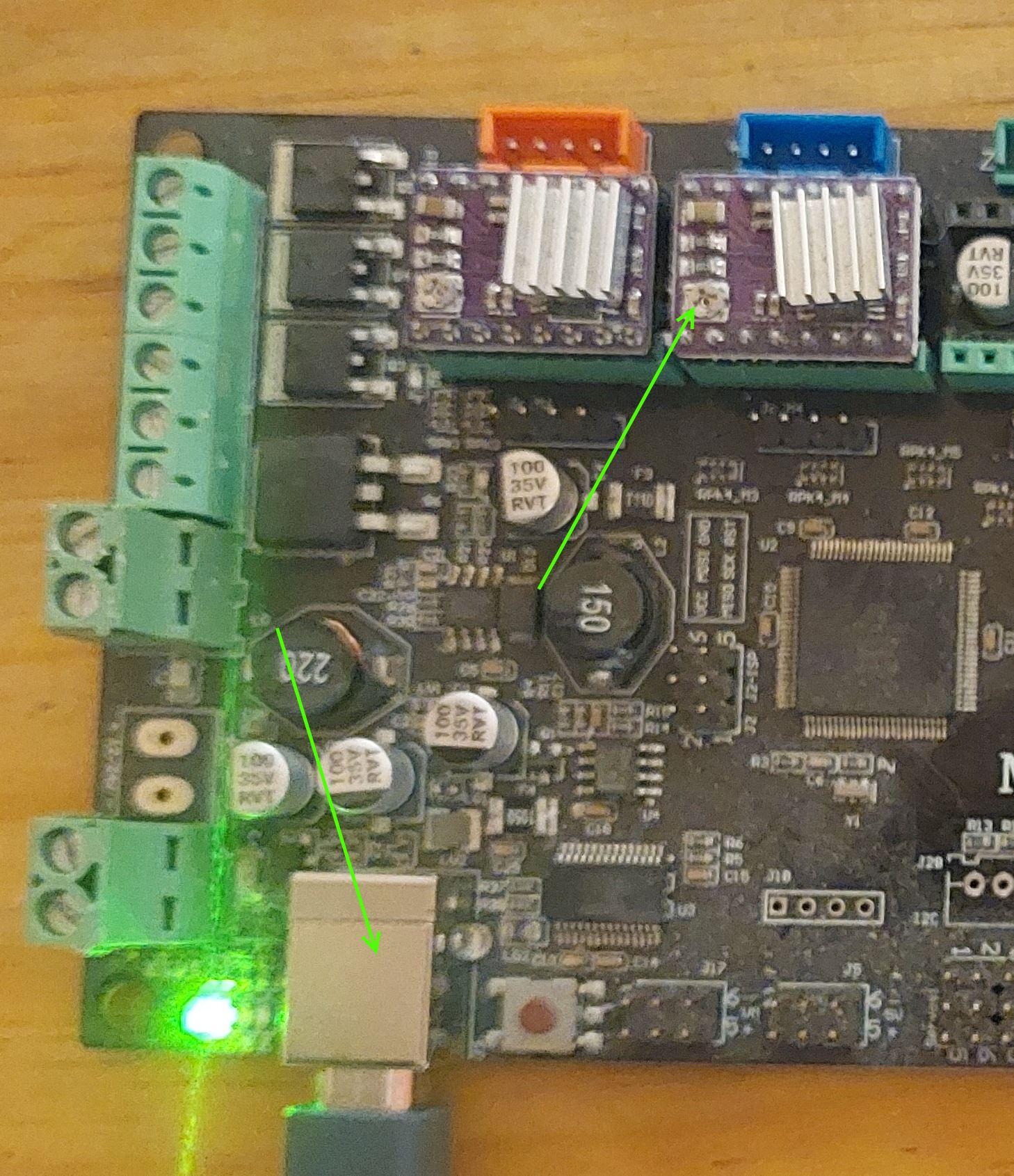
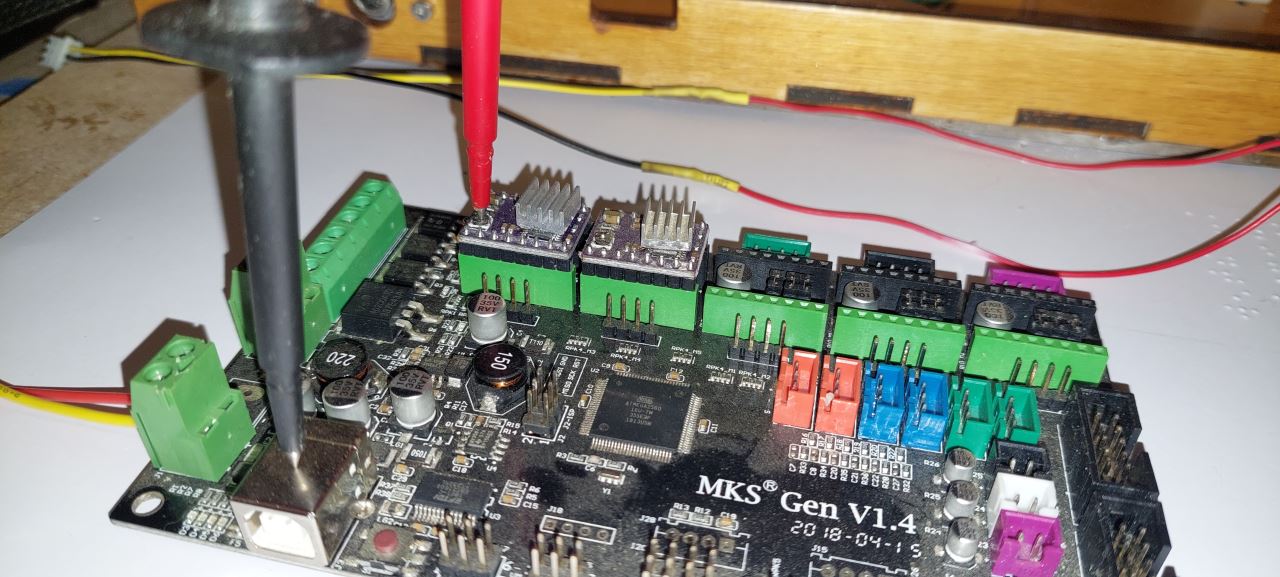
The measured voltage should be close to 0.6 V for DRV8825 drivers, ifthis is not the case, use a screwdriver to turn the potentiometer setting and redo the measurement.
Once the voltage measured on each driver is correct, you can move on
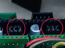
Wiring of limit switches
Wire the limit switches on the board.
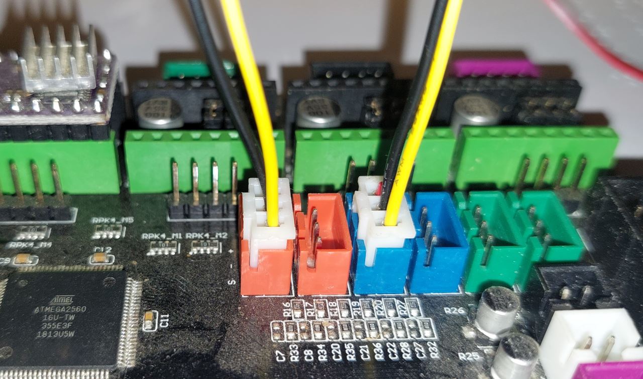
The limit switch X (carriage) must be connected to the connector of left (red)
The Y limit switch (paper detection) must be plugged into the connectorleft (blue)
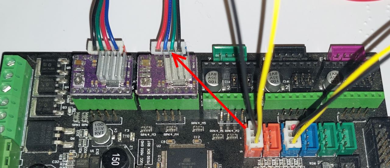
Connecting the motors to the board
Connect the motors to the control board with cables.
Motor X (carriage) must be plugged into the left connector(red)
The Y motor (paper) must be plugged into the right connector (blue)
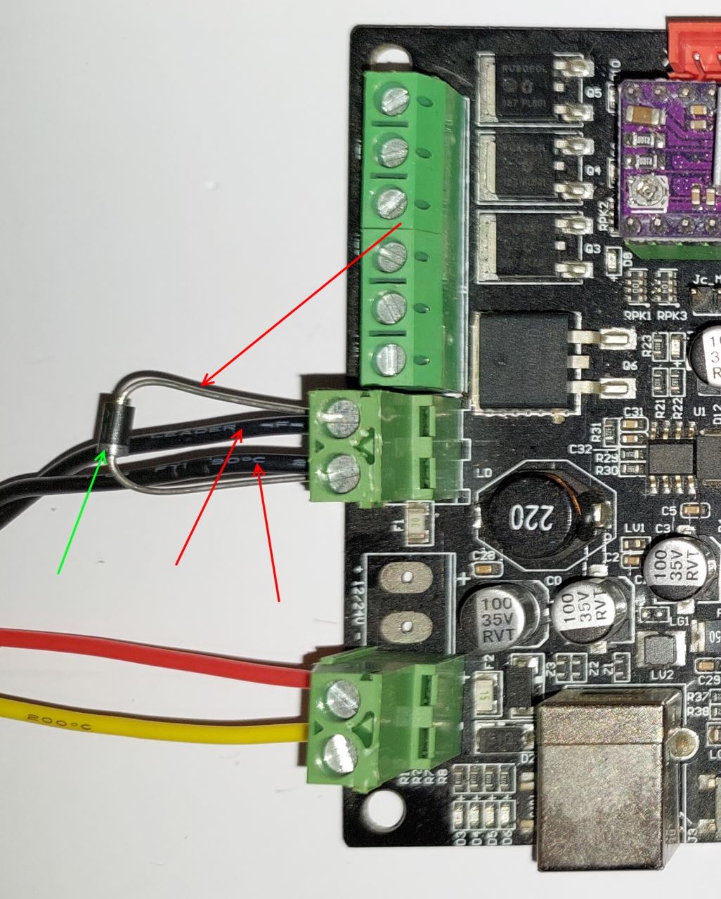
Wiring of the electromagnet
place the 2 wires of the electromagnet and the freewheel diode. Caution in the sense of the diode (white line).
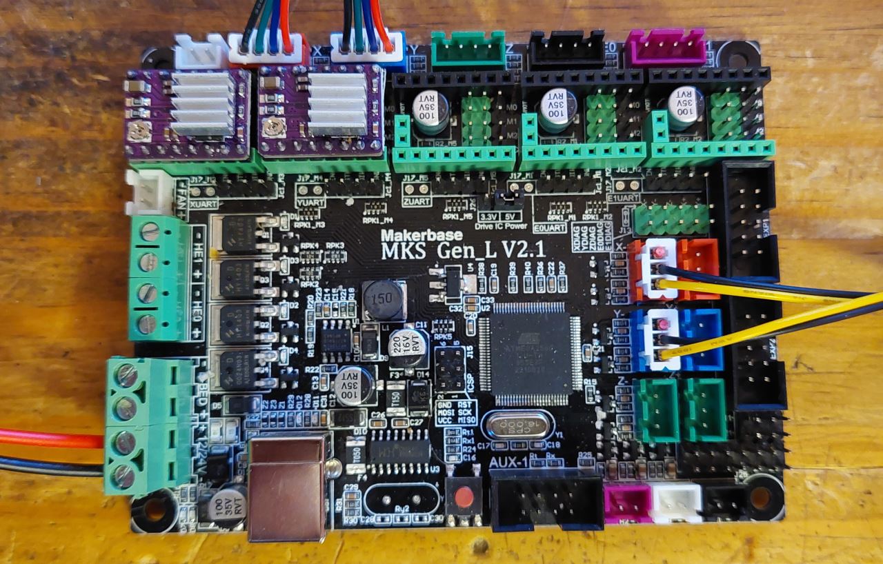
Electronic board controller mount MKS GEN-L V2.1
Equipment:
MKS GEN L V2.1 board
4 spacer M3-12
4 wide M3 washers
8 screw M3-8
Assemble the 4 spacers on the card.
Note
To be able to carry out the final adjustments easily, we recommend wiring the card outside the chassis. Once the embosser is functional, you can mount the board in the embosser.
Electronic board wiring MKS GEN-L V2.1
General diagram:
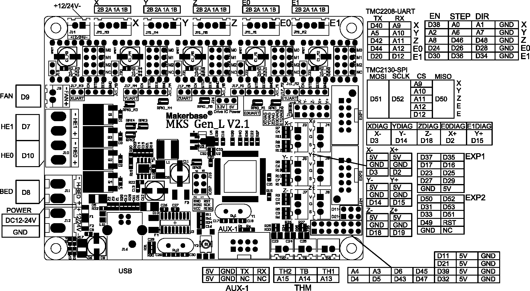
Photo of the assembled board
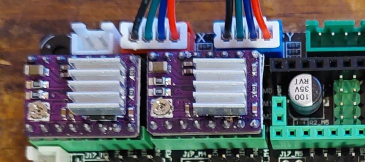
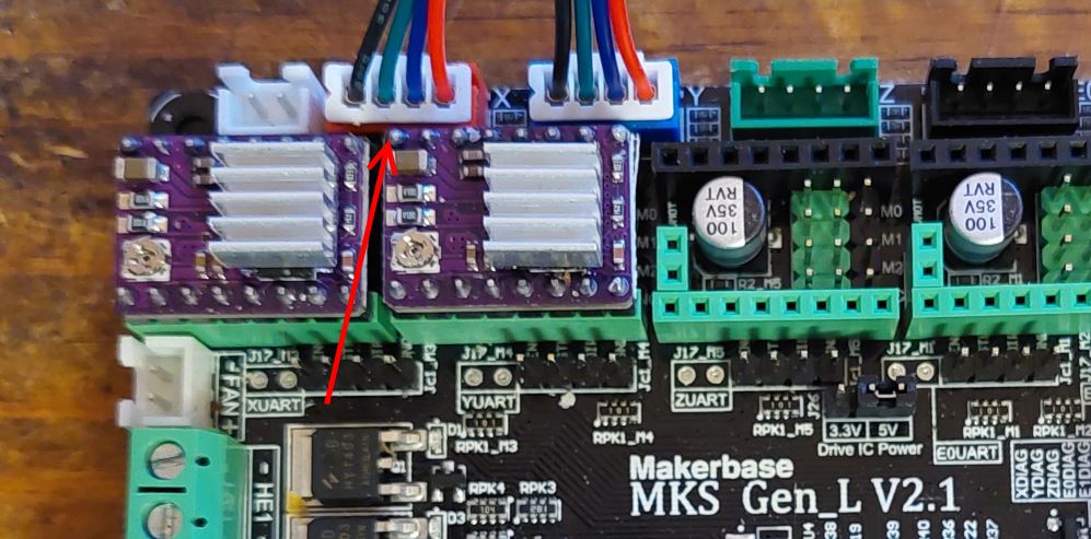
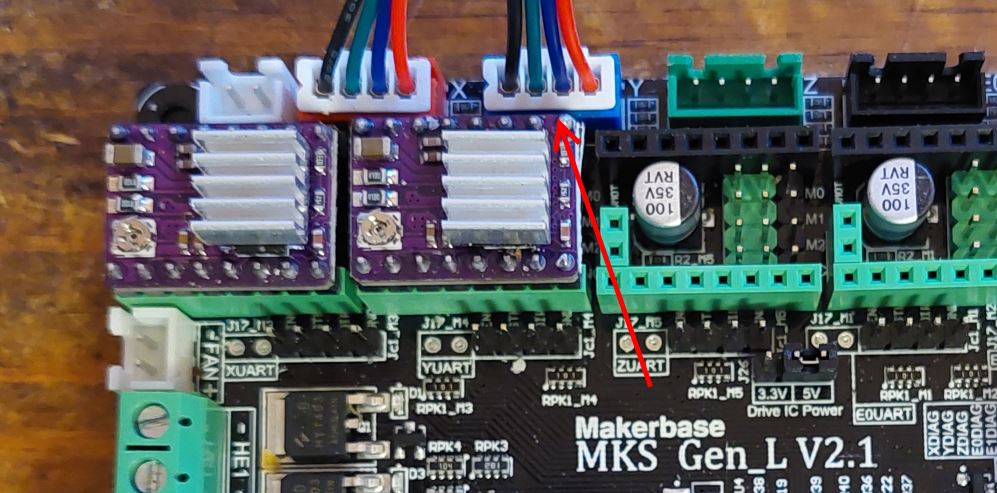
Laying the drivers on the electronic board MKS GEN-L V2.1
Equipment:
MKS GEN-L V2.1 board
2 DRV8825 drivers
6 jumpers
If the card is not supplied already equipped with jumpers, put in the places of the drivers of engines X and Y.
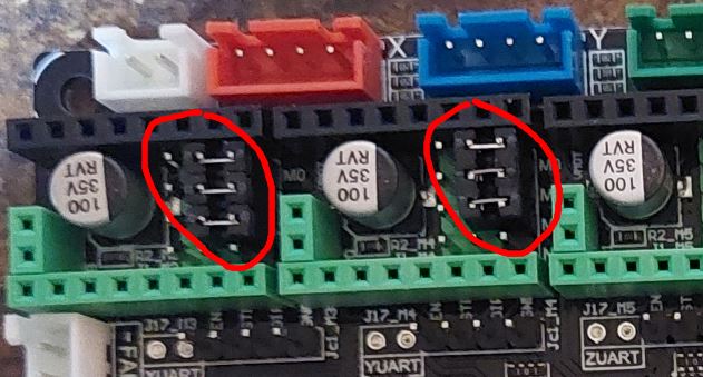
Push the drivers into X and Y slots.
12V power wiring
place the 2 wires coming from the POWER_plate socket in the terminal block of the MKS GEN-L board
Adjusting motor drivers
Note
This step must IMPERATIVELY be carried out before wiringengines.
Check that you can connect the 12V power supply to the board (a last check to avoid sparks is better :-) )
Connect the 12 V power supply to the board.
for each driver, measure, with a multimeter, the voltage between the adjustment potentiometer and mass of the USB connection.
The measured voltage should be close to 0.6 V for DRV8825 drivers, if this is not the case, use a screwdriver to turn the potentiometer setting and redo the measurement.
Once the voltage measured on each driver is correct, you can move on
Wiring of limit switches
Wire the limit switches on the MKS GEN-L board.
The limit switch X (carriage) must be connected to the connector on the top left (red)
The Y limit switch (paper detection) must be plugged into the connector on bottom left (blue)
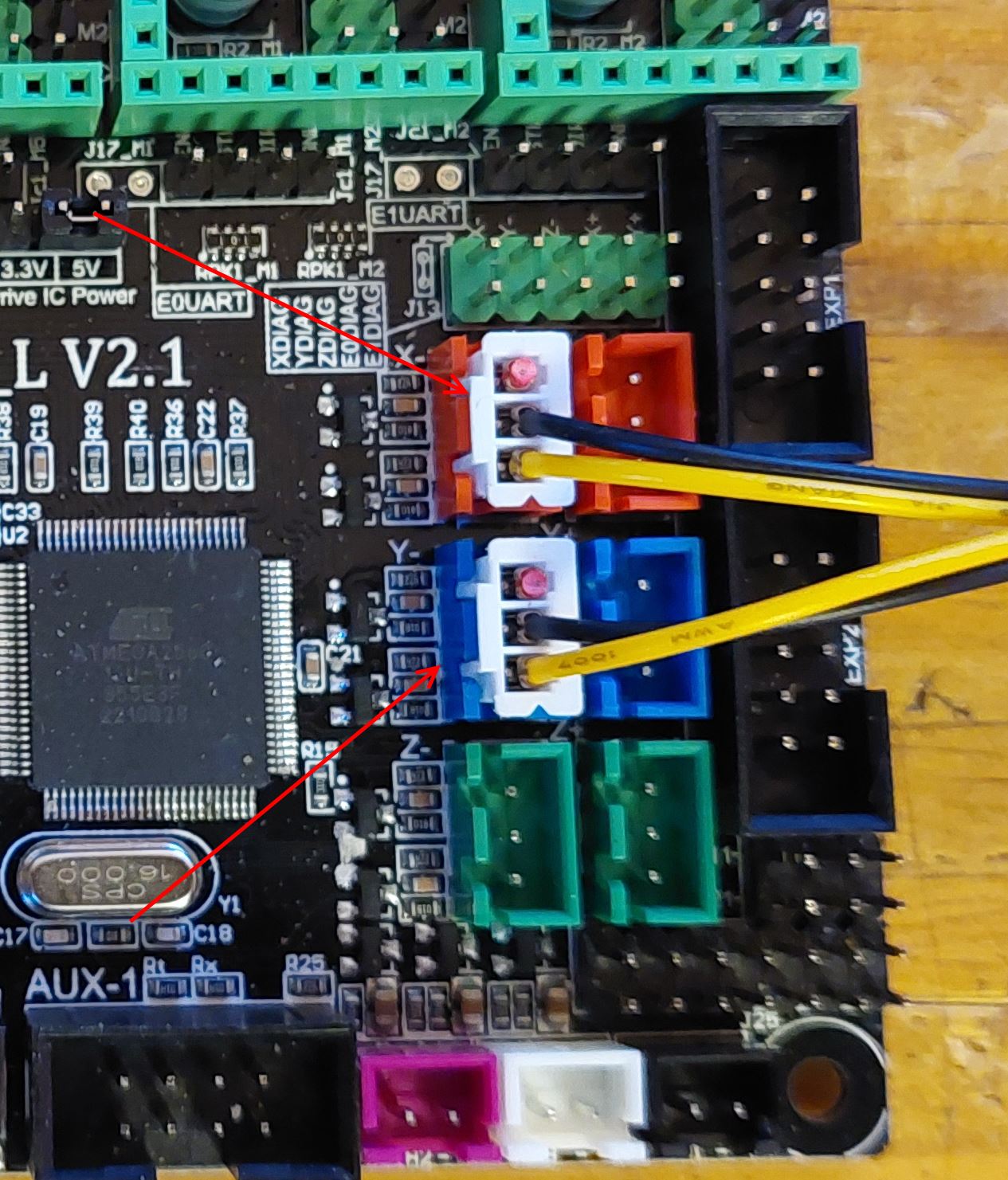
Connecting the motors to the board MKS GEN-L
Connect the motors to the control board with cables.
Motor X (carriage) must be plugged into the left connector(red)
The Y motor (paper) must be plugged into the right connector (blue)
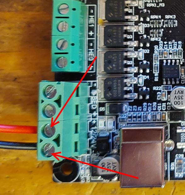
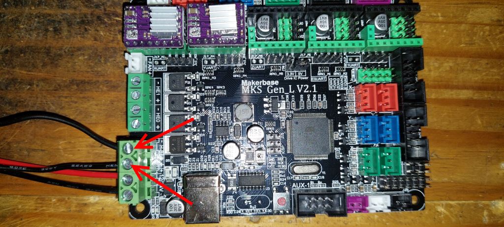
Wiring of the electromagnet MKS GEN-L 2.1
Connect the 2 solenoid wire on the HBED connector of the MKS GEN-L 2.1 board.
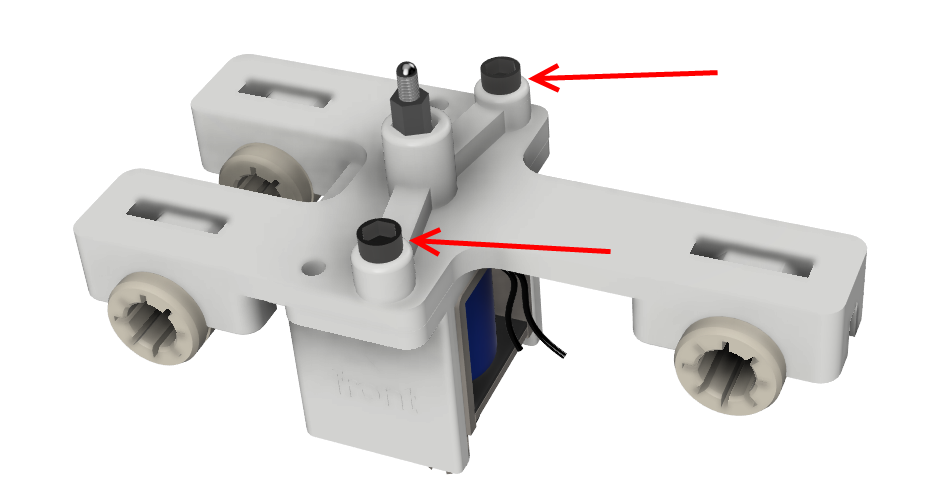
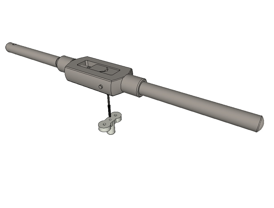
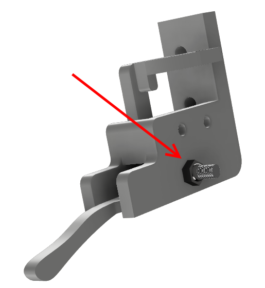
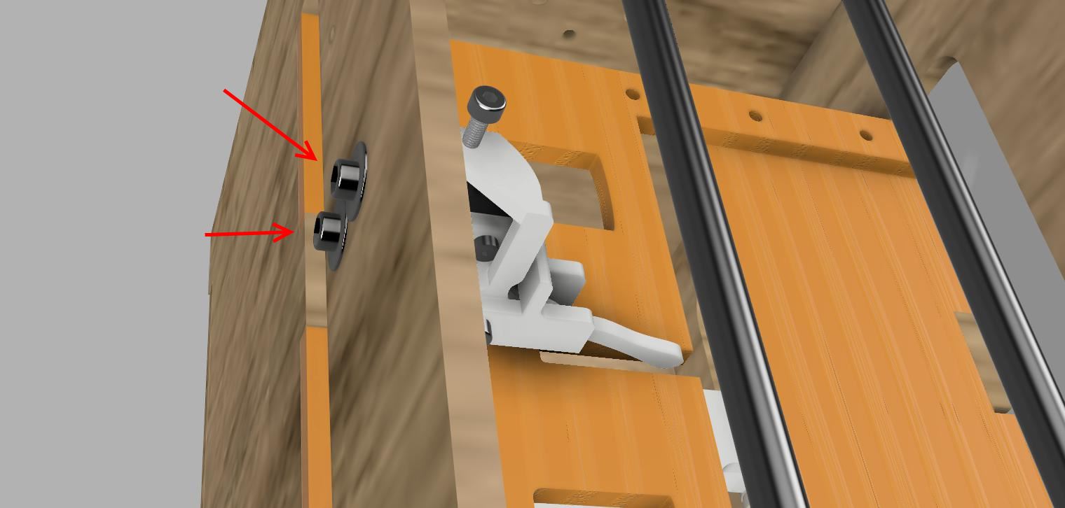
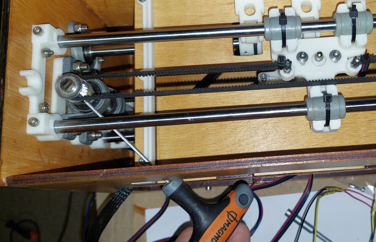
Horizontal alignment of the top carriage
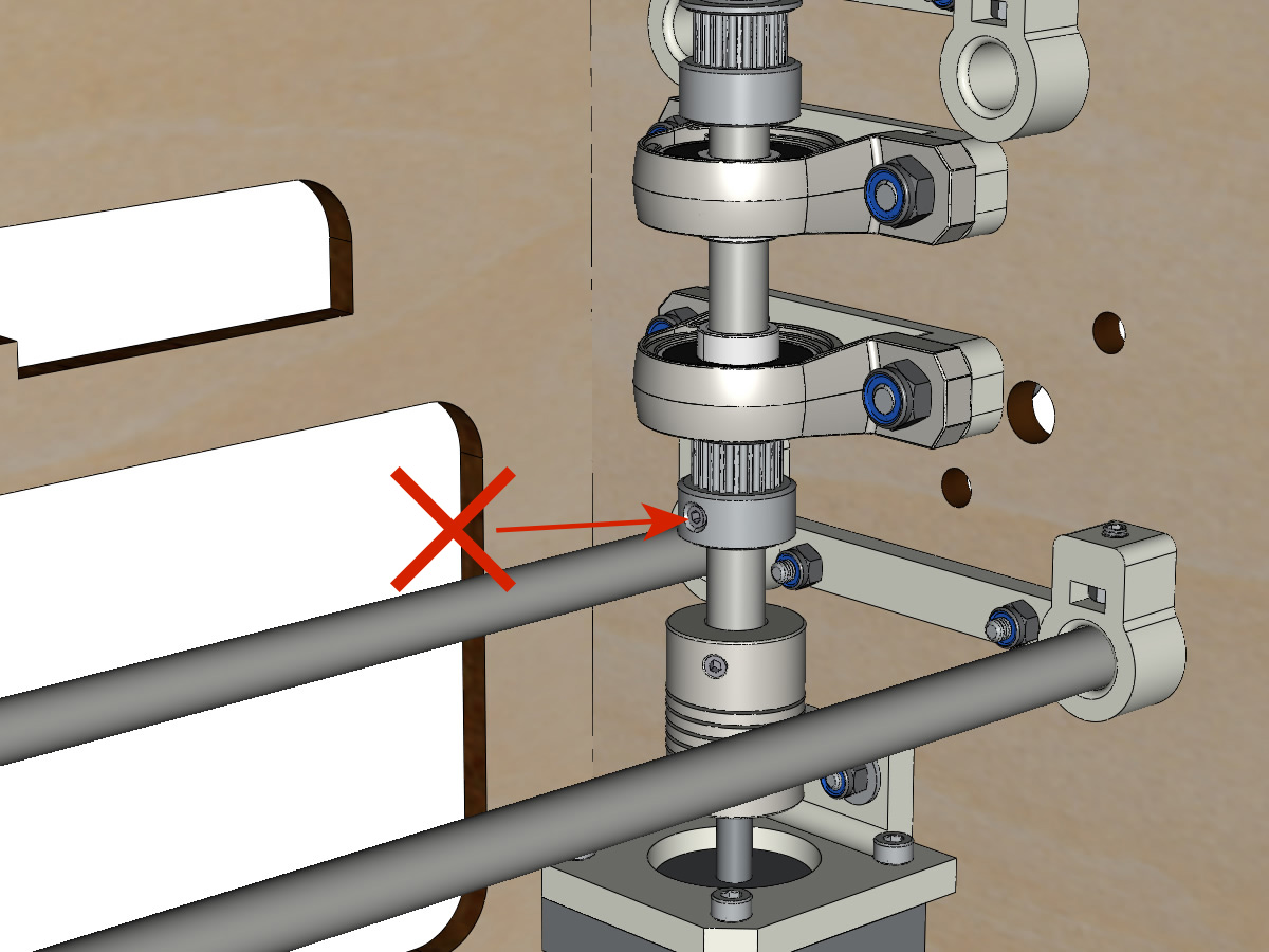
Loosen the pulley on the vertical axis to release the top carriage.
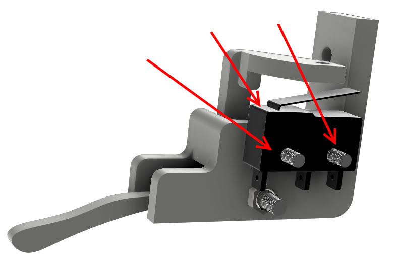
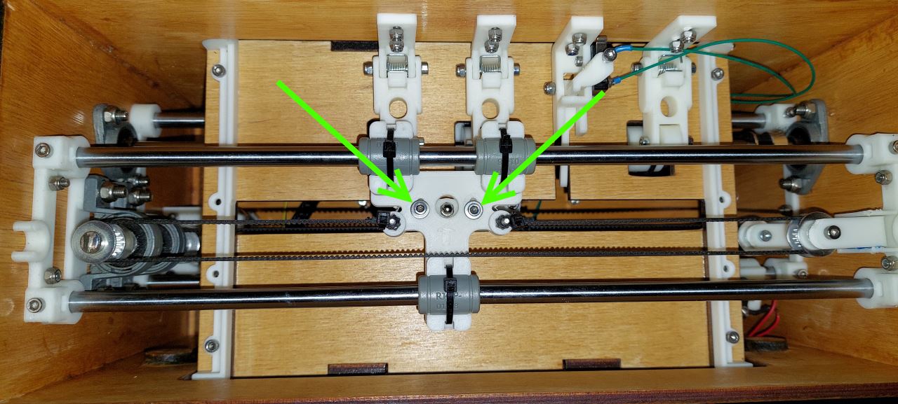
Vertical alignment of the two trolley
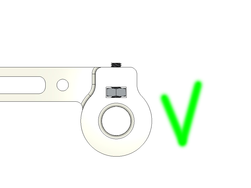
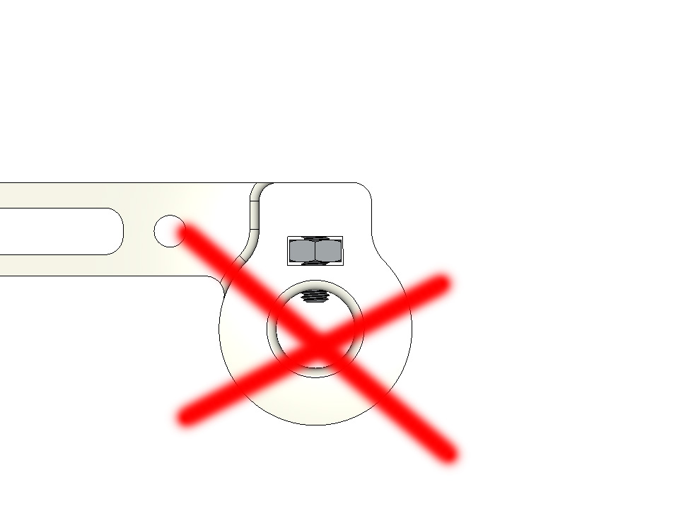
Move upper carriage to align footprint (FEMALE_shape)with the top of the Braille stylus.
Use the fixing screws of the FEMALE_shape to align the imprint with the top of the punch.
When the alignment is satisfactory, tighten the fixing screws of the FEMALE_shape.
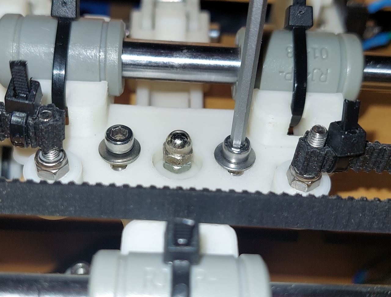
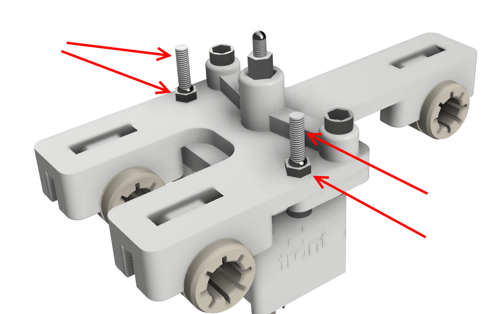
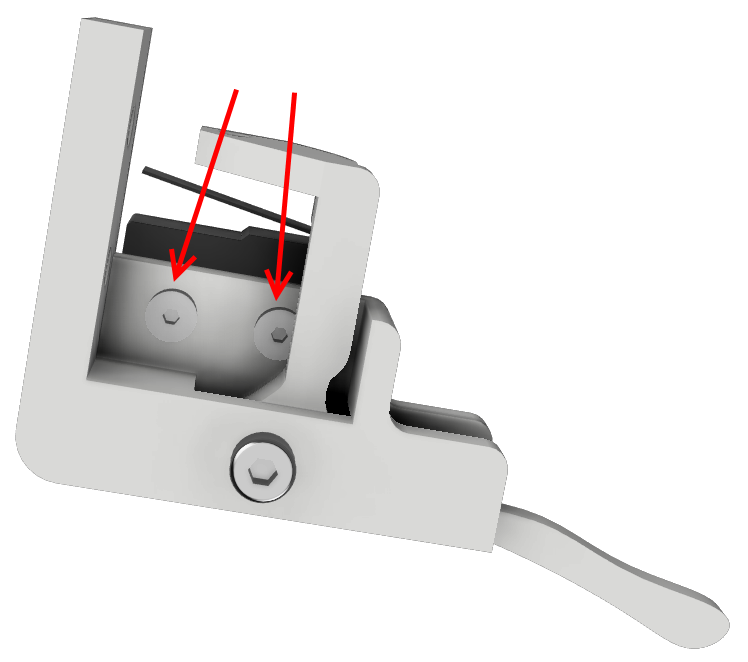
Vertical alignment of the two carriages
Loosen the pulley of the upper carriage on the vertical axis to free the top carriage.
Observing from the rear of the machine, raise the Braille stylus by pressing with the finger under the electromagnet.
Move upper carriage to align footprint (FEMALE_shape)with the top of the Braille stylus.
Logically the Braille stylus must enter slightly into the grub screw of the FEMALE_shape.
When the alignment is satisfactory, lock the upper pulley onto the vertical axis.
Carriage Adjustment and paper limit sensors (X and Y)
Adjust the position of the limit switch X. The sensor should activate before the low carriage belt attachment meets the vertical axis pulley.
With a sheet of paper, adjust the Y limit switch so that the sensor is activated when a sheet is present under the lever of the sensor. And deactivates if the sheet of paper has not yet moved the lever.
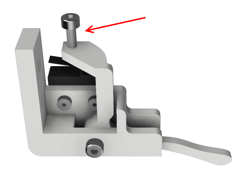
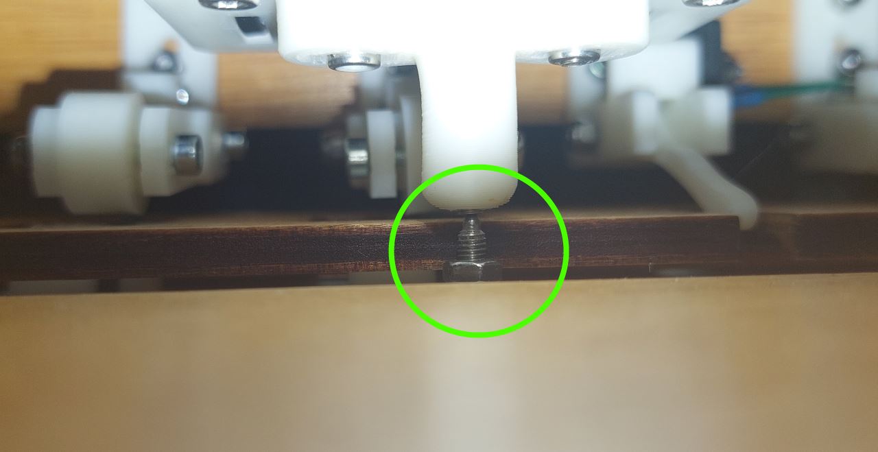
Adjusting the Braille point depth
Depending on the material you will use (paper, plastic, aluminum bobbin), you will need to adjust the height of the borrows of the high carriage using the blind nut

Closing the rear panel
Equipment:
3D printed parts : 2 X DOORLOCKER.stl
4 M3-16 screws
Tap the fixing hole of the parts DOORLOCKER
Fix DOORLOCKER parts on the rear panel. Do not tight too much, DOORLOCKER part must move easily.
Put the rear panel on the frame.
Slide the DOORLOCKER parts to lock the door.
Tighten (gently) the screws.
X and Y Margin fine tuning
By using a software like pronterface, you can tune the distance between the endstops and the 0 position on the paper sheet. This is more useful on BrailleRAP XL.
the command reference is available here : ‘<https://marlinfw.org/docs/gcode/M206.html>’_
To display the current offset values :
M206
tuning of X offset :
M206 X-xx.xx
tuning of Y offset:
M206 Y-xx.xx
To save these values in EEPROM use the command : M500